Puffin said:jives11. Thanks for the link. I used that article to carry out the mods. There seems to be a difference of opinion as to the value to use. Someome suggested as little as 4.7uf would be sufficient. I see that 100uf has been used.
Incidentally can anyone confirm that the reason I got no output from A/V input was because I removed the DC blocking caps. Will I have to bridge this or add better quality caps ?
The value of the cap depends on the value of the resistor too (as described in the link). If you want to use a better performing cap (i.e Plastic film) you will need to use a smaller value (i.e 4.7uF) as larger value caps in this material are huge.
Read the text next to the last picture at :
http://www.dogbreath.de/PS1/output/output.html
If you remove the DC blocking caps and don't replace with either a) another cap or b) a link , you will have no signal as the circuit will be open
I opened up the 5552. The Dac chip is the same as in the 1002. However the orientation of components surrounding the chip are different.
I took a pic. It seems that the DC blockng caps run along side the chip and I can only see two muting transistors marked AFR42 (not AFR49). Is it o.k to remove the DC caps and the two AFR42's ?
http://s73.photobucket.com/albums/i239/saxonsex/?action=view¤t=5552board.jpg
I took a pic. It seems that the DC blockng caps run along side the chip and I can only see two muting transistors marked AFR42 (not AFR49). Is it o.k to remove the DC caps and the two AFR42's ?
http://s73.photobucket.com/albums/i239/saxonsex/?action=view¤t=5552board.jpg
Hi
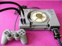
I rather like the idea of two gold
RCA's coming out above the parallel
port. I think this is a modded 5502/5522
done by Auditorium 23 in Germany some
year ago. Route the wires near to the
parallel port and use caps/resistors
and RCA's there.Could even go for
transformers if you want. there is space !
Use the old Av cord for Cd info on TV only if you
really need it. I wonder what the spindle
thing is made of in the picture? Could have
magnetic centre??
Regards
Anthony
http://www.auditorium23.de/
Attachments
AnthonyPT said:Hi
I rather like the idea of two gold
RCA's coming out above the parallel
port. http://www.auditorium23.de/
Like this one from Audio1st ?
I have been having a look back through this long, long thread and noticed that a couple of people had problems with their PS's reading discs (I assume after modification or taking the thing apart). I had some fun and games this morning. After putting back the DC caps to use the A/V out, the thing wouldn't read the disc. When I opened it up to do the job, I tried to pull off the connector that carries 4 wires from the laser mechanism and the holder parted company with the board.
Because my eyes seem to be about as good as blind pugh's it looked to me as though it was soldered (two tiny tags) on each side and that is what held it in place. I soldered it back and tried again. Nothing.
The laser would ride up and down, but do nothing else.
After some head scratching, and getting a magnifying glass. I saw that in fact the pins should be soldered to the tracks. Very tricky, but after making sure that each pin was securely soldered and actually touching the track (even with glasses on it is deceptive,because it looks as though they are a snug fit to the tracks) i.e not moving under pressure from a small screwdriver. I tried again. Success. So be careful it may not be a faulty laser.
Btw, has anyone tried using the dac's output directly to the amp which has its own DC coupling caps at the input without any caps/resistor filter after the dac? It seems to sound a bit cleaner. Is this safe? Should I place a resistor across the + and gnd of the output rcas? Thanks for your inputs.
D0Hbert said:Btw, has anyone tried using the dac's output directly to the amp which has its own DC coupling caps at the input without any caps/resistor filter after the dac? It seems to sound a bit cleaner. Is this safe? Should I place a resistor across the + and gnd of the output rcas? Thanks for your inputs.
I agree that it does sound better but you need something to attenuate the signal anyway, so when I put a 50K pot between my t-Amp and the DAC I got a wierd DC Offset at my speakers....
So I put a set of caps before the pot and all is well.

Puffin said:Audio1st. I am a bit late in getting to the PS mods, but I see in your post of Feb 2006 that you came straight off pins 15 & 16 of the chip. You say you have to remove two 10uf caps. Can you identify where these are ?
Hello Puffin, you seem to be struggling with the concept of bypassing the output stage. You can't have a new output and leave the original connected as well..
I removed C423 & C424, soldered wires to the two exposed pads nearest the chip, then add your caps (at least 2.2uf) of choice to the other end of the wires, then solder the other end of your new caps to new phono sockets. Add a ground wire between the phono sockets ground and the boards ground. Add a resistor (I used 100k ) between centre terminal of each phono and the ground side of each phono, done!
The AV out socket can still be used for video but no sound from here anymore..
D0Hbert said:Hi lostcause, we actually have the same setup. I use my psx with a amp4 t-amp, but the amp has dc blocking caps after the 50k pot I used. DC voltage is present before the caps, but if I measure the line after the input cap of the amp, its dead 0v dc.
Virtually the same setup indeed.
That's the problem though, if I had DC going through the pot then I got a wierd offset when rotating said pot!
Once I stopped turning..... the DC offset went away....No one as yet has managed to explain why so I put in another set just before the pot and that solved it.
It's probably not a good idea to have DC on the pot wiper anyway so .....
EDIT: I did install the DC trim circuit at the inputs of my amp so that may have something to do with it?????
I have now carried out the mods, takng the output off the pads by pins 15 & 16. I am using some 4.7uf poly caps as I had them lying around. Wow, what a transformation. The bass is a little full for me, so I will experiment with other cap values and maybe try 47k resistors ?
- Home
- Source & Line
- Digital Source
- Playstation as CD-player