At last
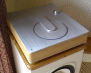
Well then ……. between starting a new job, going on holiday and installing new windows in the house I have managed to get my PS1/amp combo up and running ……… and it sounds absolutely superb. It may not be complete but the way things are panning-out it never will be! The remote volume still needs to be installed and the CD cover’s release/opening mechanism is still in my top drawer!
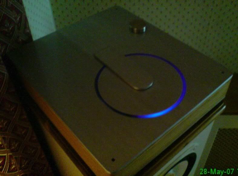
As you can see it is minimalist! I didn’t really want to have a volume knob on there so when the remote’s installed…… the knob will disappear. There aren’t even any connectors on the back! Everything goes through the base in a way that keeps all connection short and direct. It’s fabricated from 5mm Ali-plate with 5mm wood veneer.
It’s sat on foam at the moment because the sprung feet I have machined up still need fitting, it needs plenty of dampening due to where it resides!
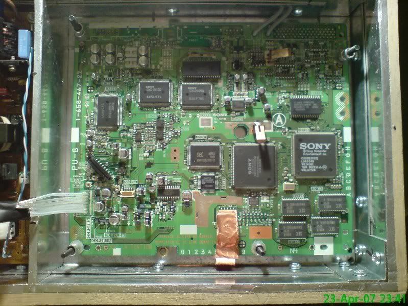
The PS1 board is stripped down to its bare bones (all connectors removed) and I have jumped straight off the DAC pins to a 50K pot and then through 4.7uf Obligatto’s directly into my heavily modified Charlize amp. There is a strange Phenomenon with this arrangement but in the interests of purity I have left out all non-essential components.
I did try Jurgen's Jfet buffer and although it sounded good I didn’t really need any more volume and it seemed to colour the music somewhat. My FE207E MLTL’s don’t need much driving. This is also on the test bench to replace the alps blue…
The SMPS is stock except for the new blue LED of course!
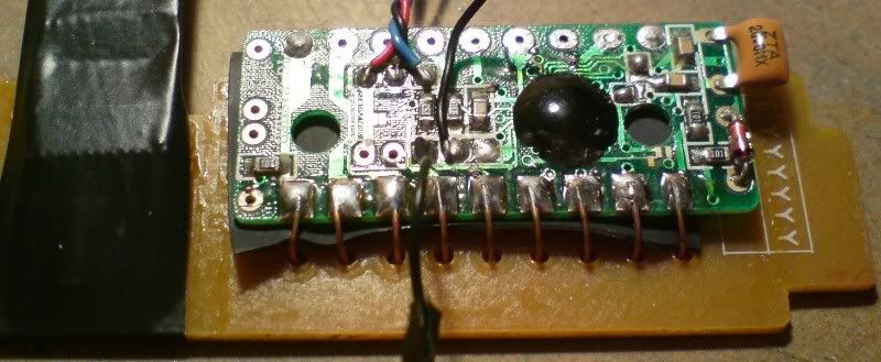
The CD remote is stashed under the board in its own protective case with the ribbon cable shrouded in copper tape to ensure the signals stay clean. The LED and sensor are then located on the underside of the case to keep the discrete clean lines I wanted. The original ground schematic has been retained using that new steel top cover which is isolated from the case.
I did have an issue with it a couple of weeks back on the test bench but after investigating further I found that I had inadvertently connected the boards ground to my safety earth through one of the fixing bolts… not recommended!
For those interested in the amp….. Input caps replaced as above and servo’s on the inputs that completely remove all DC, the feedback resistors 0603’s are soldered directly on the pins of the TA2020 (damn fiddly but I’m getting the hang of these SMD’s now). The output inductors are homebrew ferrite toroids that are mounted under the board with a separate ground plane in-between to isolate them from the rest of the board. Input wires are shielded and I may shield the speaker cables. The chip bolted/sandwiched between two sections of aluminium.
The 20V SMPS has a regulator board after it (currently set @ 13.4V) to smooth things out and a relay circuitto soft start the amp after the playstation intro has finished. I did try different stiffener caps in here as well but there was no audible difference at my listening levels.
All in all I’m very pleased with the results, visually and audibly, the base is strong and goes very low whilst the mid/top end has a wide soundstage and excellent separation. The blacks are very black with only a very faint hiss @ full volume with your ear pressed against the speakers.
My thanks to all that have helped in the evolution of my amp, Mick and the rest of the guy’s here as well as the class D chaps… especially Panomaniac who has taught me a lot over the last couple of years
Well then ……. between starting a new job, going on holiday and installing new windows in the house I have managed to get my PS1/amp combo up and running ……… and it sounds absolutely superb. It may not be complete but the way things are panning-out it never will be! The remote volume still needs to be installed and the CD cover’s release/opening mechanism is still in my top drawer!
As you can see it is minimalist! I didn’t really want to have a volume knob on there so when the remote’s installed…… the knob will disappear. There aren’t even any connectors on the back! Everything goes through the base in a way that keeps all connection short and direct. It’s fabricated from 5mm Ali-plate with 5mm wood veneer.
It’s sat on foam at the moment because the sprung feet I have machined up still need fitting, it needs plenty of dampening due to where it resides!
The PS1 board is stripped down to its bare bones (all connectors removed) and I have jumped straight off the DAC pins to a 50K pot and then through 4.7uf Obligatto’s directly into my heavily modified Charlize amp. There is a strange Phenomenon with this arrangement but in the interests of purity I have left out all non-essential components.
I did try Jurgen's Jfet buffer and although it sounded good I didn’t really need any more volume and it seemed to colour the music somewhat. My FE207E MLTL’s don’t need much driving. This is also on the test bench to replace the alps blue…
The SMPS is stock except for the new blue LED of course!
The CD remote is stashed under the board in its own protective case with the ribbon cable shrouded in copper tape to ensure the signals stay clean. The LED and sensor are then located on the underside of the case to keep the discrete clean lines I wanted. The original ground schematic has been retained using that new steel top cover which is isolated from the case.
I did have an issue with it a couple of weeks back on the test bench but after investigating further I found that I had inadvertently connected the boards ground to my safety earth through one of the fixing bolts… not recommended!
For those interested in the amp….. Input caps replaced as above and servo’s on the inputs that completely remove all DC, the feedback resistors 0603’s are soldered directly on the pins of the TA2020 (damn fiddly but I’m getting the hang of these SMD’s now). The output inductors are homebrew ferrite toroids that are mounted under the board with a separate ground plane in-between to isolate them from the rest of the board. Input wires are shielded and I may shield the speaker cables. The chip bolted/sandwiched between two sections of aluminium.
The 20V SMPS has a regulator board after it (currently set @ 13.4V) to smooth things out and a relay circuitto soft start the amp after the playstation intro has finished. I did try different stiffener caps in here as well but there was no audible difference at my listening levels.
All in all I’m very pleased with the results, visually and audibly, the base is strong and goes very low whilst the mid/top end has a wide soundstage and excellent separation. The blacks are very black with only a very faint hiss @ full volume with your ear pressed against the speakers.
My thanks to all that have helped in the evolution of my amp, Mick and the rest of the guy’s here as well as the class D chaps… especially Panomaniac who has taught me a lot over the last couple of years
Attachments

Very nice work. It looks good.
Can you show a picture where the top cover is open?
There is one point I dont really understand: why dont you put the output cap BEFORE the pot. Then the pot would not get any DC and its lifetime would be longer (and probably it is crackling now). And why do you need the servo when you have a cap just in front?
Cheers
Mick
Mick_F said:Very nice work. It looks good.
Can you show a picture where the top cover is open?
There is one point I dont really understand: why dont you put the output cap BEFORE the pot. Then the pot would not get any DC and its lifetime would be longer (and probably it is crackling now). And why do you need the servo when you have a cap just in front?
Cheers
Mick
Hi Mick, thanks for the compliment, I wish I could give more time to finish the 'little bits' off!
The Charlize (or any other T-amp) have 2,4V Bias on the input so you have to block that from grounding at the pot. There is no crackling as yet but there certainly is a strange DC offset when you turn the knob (as linked in the post).
I agree that this is not ideal and I will more than likely add a couple more caps before the pot deteriorates.......it sounds so good at the moment though....

The T-amps generate a small amount of offset so the servo is just to null whatever is there. Before fitting mine was about 80mv and 110mv.
I'd love to take a picture with the lid open but the mechanism is still in my top drawer so I can't keep it open
Well I gave in yesterday and put in another set of caps before the pot.
Everything is as it should be now but I have lost some of the low volume bass presence, maybe it's better with Jurgen's buffer back in there?...it's pretty close...
I would like to keep the SMPS in there but would like to improve it, what could I do guys? Just replace some critical parts or maybe make a whole new one?... I wonder if the later models have the same supply voltage in a better package?
As far as I remember, the build quality goes down with later models. I believe, the second version of the smps (manufacturer is Nichicon) is the best.
However a linear PSU (see my site) is a big improvement. Using relatively small trafos, you may be able to build it such that it fits in your case.
Mick
However a linear PSU (see my site) is a big improvement. Using relatively small trafos, you may be able to build it such that it fits in your case.
Mick
Crikey! You reckon you could get it into the same envelope as the current SMPS?...Now I'm interested!Using relatively small trafos, you may be able to build it such that it fits in your case.
Got any idea where I could get trafos that size?
Cheers
Lee
Well, you dont need much VA for the PS1. You could put the trafo in an upright position, so the depth of your case determines the allowed diameter of a toroid. You can also use print mount trafos.
The minimum VA you need is about 8V*1A + 4V*1A = 12 VA. Double this for some headroom. 24 or 30 VA trafos are small. Eg. No. 9530304 or 1166240 from Farnell....
The main point is that you have to get rid of the heat. The LMs and the pass transistor in the second stage need cooling. You can probably mount them on the inside of an outer wall of your case.
Mick
Mick_F said:Well, you dont need much VA for the PS1. You could put the trafo in an upright position, so the depth of your case determines the allowed diameter of a toroid. You can also use print mount trafos.
The minimum VA you need is about 8V*1A + 4V*1A = 12 VA. Double this for some headroom. 24 or 30 VA trafos are small. Eg. No. 9530304 or 1166240 from Farnell....
The main point is that you have to get rid of the heat. The LMs and the pass transistor in the second stage need cooling. You can probably mount them on the inside of an outer wall of your case.
Mick
OK, thanks for the link Mick, the print mount will fit.......so are you saying to use one trafo and two regs or two complete power supplies?
One of the 1166240's would leave plenty of room for the rest of the components and I can cool it by attaching to the base plate.
EDIT: OK so I will need 2 trafos
thats going to be a squeeze but should just about fit.....this is getting interesting....My favourite linear PSU is described here . It involves double regulation for the 3.6V rail.
For a simpler version, you may discard the second stage by regulating directly to the desired voltage in the first stage (use an appropriate trimmer). Then you only have to cool two devices (the LM317's).
Mick
For a simpler version, you may discard the second stage by regulating directly to the desired voltage in the first stage (use an appropriate trimmer). Then you only have to cool two devices (the LM317's).
Mick
Is it possible/recomended to use a 30VA for both?
These guys do one that would fit and I could get 2 x 12V lines off it....enough headroom?
Anyone got the sizes of the powerboard to hand?
These guys do one that would fit and I could get 2 x 12V lines off it....enough headroom?
Anyone got the sizes of the powerboard to hand?
Mick_F said:30VA for both rails will work. 2 x 12 V is just fine.
Mick
Thanks Mick......now to design a board that will fit!
At least I have more room with only one transformer in there....-
la-li-lu-le-lo said:I have a SCPH-1001, but unfortunately the cd drive is screwed up. Do you think it would hurt anything to transplant one from a SCPH-9001? I'm sure that it would work, but I'm just worried that it could hurt the audio quality.
I'm not 100% on this one but the connector (ribbon cable) on the later models is different due to the transport being relocated......but if you can twist it into position it should be the same pin-out
Re: At last
Wow - great job. it looks fantastic. I particularly like the blue light emerging from under the hood.
BTW , on the subject of offsets, did you ever figure out why the DC blocking caps on the PS1 board appear to be the wrong way round ? Much earlier i this thread there was some discussion while we were trying to figure out how to bypas them. Maybe it's connected with the Mon0-iser black cube for when connecting UHF TV, but your discussion of DC offset remined me that we never figured it out. The +ve terminals appear to face to ward the outputs ?
Lostcause said:Well then ……. between starting a new job, going on holiday and installing new windows in the house I have managed to get my PS1/amp combo up and running ……… and it sounds absolutely superb. It may not be complete but the way things are panning-out it never will be! The remote volume still needs to be installed and the CD cover’s release/opening mechanism is still in my top drawer!
As you can see it is minimalist! I didn’t really want to have a volume knob on there so when the remote’s installed…… the knob will disappear. There aren’t even any connectors on the back! Everything goes through the base in a way that keeps all connection short and direct. It’s fabricated from 5mm Ali-plate with 5mm wood veneer.
It’s sat on foam at the moment because the sprung feet I have machined up still need fitting, it needs plenty of dampening due to where it resides!
The PS1 board is stripped down to its bare bones (all connectors removed) and I have jumped straight off the DAC pins to a 50K pot and then through 4.7uf Obligatto’s directly into my heavily modified Charlize amp. There is a strange Phenomenon with this arrangement but in the interests of purity I have left out all non-essential components.
I did try Jurgen's Jfet buffer and although it sounded good I didn’t really need any more volume and it seemed to colour the music somewhat. My FE207E MLTL’s don’t need much driving. This is also on the test bench to replace the alps blue…
The SMPS is stock except for the new blue LED of course!
The CD remote is stashed under the board in its own protective case with the ribbon cable shrouded in copper tape to ensure the signals stay clean. The LED and sensor are then located on the underside of the case to keep the discrete clean lines I wanted. The original ground schematic has been retained using that new steel top cover which is isolated from the case.
I did have an issue with it a couple of weeks back on the test bench but after investigating further I found that I had inadvertently connected the boards ground to my safety earth through one of the fixing bolts… not recommended!
For those interested in the amp….. Input caps replaced as above and servo’s on the inputs that completely remove all DC, the feedback resistors 0603’s are soldered directly on the pins of the TA2020 (damn fiddly but I’m getting the hang of these SMD’s now). The output inductors are homebrew ferrite toroids that are mounted under the board with a separate ground plane in-between to isolate them from the rest of the board. Input wires are shielded and I may shield the speaker cables. The chip bolted/sandwiched between two sections of aluminium.
The 20V SMPS has a regulator board after it (currently set @ 13.4V) to smooth things out and a relay circuitto soft start the amp after the playstation intro has finished. I did try different stiffener caps in here as well but there was no audible difference at my listening levels.
All in all I’m very pleased with the results, visually and audibly, the base is strong and goes very low whilst the mid/top end has a wide soundstage and excellent separation. The blacks are very black with only a very faint hiss @ full volume with your ear pressed against the speakers.
My thanks to all that have helped in the evolution of my amp, Mick and the rest of the guy’s here as well as the class D chaps… especially Panomaniac who has taught me a lot over the last couple of years
Wow
- great job. it looks fantastic. I particularly like the blue light emerging from under the hood.BTW , on the subject of offsets, did you ever figure out why the DC blocking caps on the PS1 board appear to be the wrong way round ? Much earlier i this thread there was some discussion while we were trying to figure out how to bypas them. Maybe it's connected with the Mon0-iser black cube for when connecting UHF TV, but your discussion of DC offset remined me that we never figured it out. The +ve terminals appear to face to ward the outputs ?
Thanks Jives, it's emerging through clear casting resin that's slightly opaque but I'm going to have to paint the inners white to get an all-round glow... a bit localised at the moment.Wow - great job. it looks fantastic. I particularly like the blue light emerging from under the hood.
On the DC blocking side.... I suppose it doesn't really matter which way the cap is orientated, I wonder if it's because of the automated sytem they used then? There was no reason to program the robot to fit them symetrically....so they didn't..?
la-li-lu-le-lo said:I have a SCPH-1001, but unfortunately the cd drive is screwed up. Do you think it would hurt anything to transplant one from a SCPH-9001? I'm sure that it would work, but I'm just worried that it could hurt the audio quality.
I've just transplanted a 9002 (UK units) drive into a 1002 and it is working just fine. I had to modify the 9002 drive by cutting off 3 plastic legs and a plastic bracket, and the 1002 cover opening had to have one edge slightly enlarged.
Hello all,
Been read thru this entire thread for the past few days and my eyes are bleeding Pretty darn long. I've also read thru Mick site regarding the tweak he's mentioned.
Currently have 2 versions of the PS1 SCPH100x(japan version) and SCPH55X2. Both are unmodified at this present time and in the process of slowly doing.
My question is regarding modifiying the output stage.
can the Swenson mods replace Mick current setup and if so is there anything I should be aware to follow thru this mod?
http://johnswenson1.home.comcast.net/3950_mod/Toshiba_3950_3960_mods.html
my other question is regarding replacing the Diode.
would these work CREE Silicon Carbide "high voltage" Schottky Diodes
10 Amp, 600V,TO-220, 2-lead or should I stick with MSR860 soft recovery diode? only problem not sure where to get them.
Located in Toronto, Canada.
Pretty new to mod on audio. Sorry for the lame questions. I am sure I'll have more noob question in the future.
cheers
Been read thru this entire thread for the past few days and my eyes are bleeding
Pretty darn long. I've also read thru Mick site regarding the tweak he's mentioned.Currently have 2 versions of the PS1 SCPH100x(japan version) and SCPH55X2. Both are unmodified at this present time and in the process of slowly doing.
My question is regarding modifiying the output stage.
can the Swenson mods replace Mick current setup and if so is there anything I should be aware to follow thru this mod?
http://johnswenson1.home.comcast.net/3950_mod/Toshiba_3950_3960_mods.html
my other question is regarding replacing the Diode.
would these work CREE Silicon Carbide "high voltage" Schottky Diodes
10 Amp, 600V,TO-220, 2-lead or should I stick with MSR860 soft recovery diode? only problem not sure where to get them.
Located in Toronto, Canada.
Pretty new to mod on audio. Sorry for the lame questions. I am sure I'll have more noob question in the future.
cheers
- Home
- Source & Line
- Digital Source
- Playstation as CD-player