dommi here the schematic for the regulator.
nice psu the separate transformers are a good choice.
i didn`t know about the snubber do you know how it is calculated?
Mick_F said:Dommi, I am in the course of building a PSU. I will use two separate toroidals (10 V), one for the 7.6 V and one for the 3.6 V output. I will use two LM317 regulators in a regular circuit. The capacity will be someting like 1000uF before, 100uF and a snubber after the regulators.
Mick
nice psu the separate transformers are a good choice.
i didn`t know about the snubber do you know how it is calculated?
back said:dommi here the schematic for the regulator
http://ourworld.compuserve.com/homepages/Bill_Bowden/page12.htm#317pass.gif
Hi
Besides finding a 1002 Playstation for
AUD$39 dollars. I went into Dick Smiths because on P.158
of their catalogue they had the Joytech DVD PS2 remote that
does some IR functions with the PS1. To my surprise they are
an end of line product @ Aud$2.47 dollars each.
Part Number YG2048 I bought two and may go for more. This was
in the Fremantle store. Now to find some more PS1#1002 units in
good condition.
It is sounding good and has 3 Months warranty. Will Tweak it
after that runs out ! The YG2048 has screws not glue!
Regards
AnthonyPT
NB
The YG2048 does not seem to be in the online catague!
Dommi said:
You have to adjust the Laser at 11,4 mV for short connection cable and 24,4 mV for long connection cable. Turn on the PS, push the cover close switch, you have to messure while the laser moves up and down.
Hi Dommi, I hope this isn't a silly question, but what do you mean by long and short connections? Cheers..
audio1st said:
Hi Dommi, I hope this isn't a silly question, but what do you mean by long and short connections? Cheers..
Hi,
i meen the kopper cable to connect the laserunit with the board.
The original laserunit and the laserunit of the PS ONE have a short cablefor connection. The laserunit AAM,ACM,BAM have to be adjusted to 11,4 mV, the AAM and AEM to 24,4 mV
Dommi
Re: Re: Re: mass damping
Hi,
the blue led is to minimize difuse reflection from the CD. The blue light absorb the lense light. In my config i can't determine any differences with or without blue led. But Michael Methe find out in his configuration that it sounds better with blue led. I let it inside. You have to check it out in your config.
For transport mount i can tell you that is verry much better to fix the transport with thread and nuts. You can see it if you play a CD. Look on the laserlense and you can see how it moves. Because of the movement of the complete unit the lense is steady moving back and forward to compensate the movement of the unit. With a fixed unit the movement of the lense is minimized.
Try it and hear !!
Regards Dommi
jives11 said:
Thanks Dommi,
What is the reason for the blue LED ?
I assume i't not like the Car or PC case modders ("pimp my playstation")
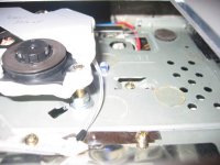
I noticed that the transport is supported in 3 rubber tubes, but on one side this floating is damped by a plastic tab which rubs against a small rubber pad attached to the metal subchasis. I guess removing the tab and the rubber pad will allow the transport to 'float' better ?
Hi,
the blue led is to minimize difuse reflection from the CD. The blue light absorb the lense light. In my config i can't determine any differences with or without blue led. But Michael Methe find out in his configuration that it sounds better with blue led. I let it inside. You have to check it out in your config.
For transport mount i can tell you that is verry much better to fix the transport with thread and nuts. You can see it if you play a CD. Look on the laserlense and you can see how it moves. Because of the movement of the complete unit the lense is steady moving back and forward to compensate the movement of the unit. With a fixed unit the movement of the lense is minimized.
Try it and hear !!
Regards Dommi
Attachments
Mick_F said:
Toroidals are "Ringkerntrafos".
Snubbers are serial RC networks (like a Zobel) to decrease the ESR of the power supply. Have a look at this page for my implementation of CarlosFMs famous PSU. The snubber is the RC network just before the output.
Mick
pieroh said:
Hi Dommi,
if you use a tube output stage you could use the heater windings at the transformer. The 6,3V to build a regulated supply for the 3,6V and the 12,6V-AC for the 7,6V supply.
Peter
@mick
it looks good, i have to think about to use a external power supply for PSU and Tube stage. If your power supply is ready can you please discribe the changes at the sound of PS ? I´m not shure if it is a good idea to change the power supply, because i think that the original pwr.supply of the ps1 after some modifications is verry verry good.
@pieroh
good idea !! But first i have to build the tube extension only, to look if it sounds better. I heard that many people tryed a tube stage, but the sound was not as good as without tube. Only Michael Methe reports a betterment. I will contact him for a shematic.
@back
Thanks for the link
BR, I wish you a merry christmas and a few peacefull day's with good music
Dommi
Dommi said:
Hi,
the blue led is to minimize difuse reflection from the CD. The blue light absorb the lense light. In my config i can't determine any differences with or without blue led. But Michael Methe find out in his configuration that it sounds better with blue led. I let it inside. You have to check it out in your config.
For transport mount i can tell you that is verry much better to fix the transport with thread and nuts. You can see it if you play a CD. Look on the laserlense and you can see how it moves. Because of the movement of the complete unit the lense is steady moving back and forward to compensate the movement of the unit. With a fixed unit the movement of the lense is minimized.
Try it and hear !!
Regards Dommi
Dommi, I am sure that the use of a blue led for absorption of stray light of the laser (or anything like that) is pure nonsense. I am a physicist and can judge this kind of statements.
It may be a powerful aid in psychoacoustics for some people, though
I will try to fix the laser unit and see how it changes. It will certainly be worth a try.
Dommi said:
@mick
it looks good, i have to think about to use a external power supply for PSU and Tube stage. If your power supply is ready can you please discribe the changes at the sound of PS ? I´m not shure if it is a good idea to change the power supply, because i think that the original pwr.supply of the ps1 after some modifications is verry verry good.
BR, I wish you a merry christmas and a few peacefull day's with good music
Dommi
I also think that just replacing the PSU because it is a switching type supply is not necessary. I have observed some problems with distinct ripple at frequencies of about 500 Hz (if I recall correctly) and instabilities. I have no time now but I will report in detail later on.
Dommi said:O.K.,
i know that someone posted a description about the allocation of the psu between the 7 pin and 5 pin psu. But i can't find it anymore. Can someone please post the config for 7 pin psu ?
Thanks a lot !!
Dommi
I dont exactly understand you question. But I guess that the difference between the 7- and 5-pin umbilicals is that in the latter the three ground leads are combined.
Finally, let me also whish all of you a very happy christmas time and all the best for 2006.
Mick
@ Mick
So i don`t get faked from the blue led
Since the last fopas with the caps i checked all modifications in blind tests if possible. Only if i had a quote of better or equal 70 % i allege that this sounds better
Mick, i'm right whan i think you've used MKS caps for the caps at the DAC ? I ordered MKP 10 caps without have a mind on the gauge
I will modify a PS for a friend without changing the case.
Oh, i forgot. I wanted to know the "Pinbelegung" of the 7 pins, so on pin 1 from the front which Voltage is there, an on. So if i try with a new pwr supply i have to make bridges from pin x to pin y.
And let me say thanks for the tip with the sockets for connect PSU and motherboard. Verry good !!!
Dommi
Dommi said:@ Mick
Mick, i'm right whan i think you've used MKS caps for the caps at the DAC ? I ordered MKP 10 caps without have a mind on the gauge
I will modify a PS for a friend without changing the case.
Oh, i forgot. I wanted to know the "Pinbelegung" of the 7 pins, so on pin 1 from the front which Voltage is there, an on. So if i try with a new pwr supply i have to make bridges from pin x to pin y.
And let me say thanks for the tip with the sockets for connect PSU and motherboard. Verry good !!!
Dommi
Dommi, I guess MKP caps are as good. I used these Wimas as I had them in my parts box.
The pinout of the umbilical is (pin 1 is on the left when looking on the psu board with the mains connector on the right):
1: 7.6 V
2: gnd
3: 3.6 V
4: gnd
5: 3.6 V
6: gnd
7: 0 V in normal operation, 3.6 V when reset is pressed.
You can leave connection 7 open, and do a reset just by switching power off and on, that will save you one wire in the connector. Somewhere in the beginning of this thread, a schematic including all the connections was shown. I am, however, too lazy to look for it right now
Best whishes to you too, back.
Mick
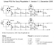
This is what I am going to build as a linear PSU for the PS1.

Two separate circuits with separate transformers (sec. 10 V) are used for the 7.6V and 3.6V needed. Both are regulated using a LM317. Trimmers R4, R6 are used to set the correct resistor value on the lower arm of the voltage divider following the regulator.
The capacitors on the adj pin to ground are used to increase ripple rejection to 80 dB. These caps are optional. If they are used, additional protection diodes (D3, D4) are recommended to prevent damage due to discharging of C4, C8.
Please let me know what you think about it. Suggestions are welcome.
Mick
Mick_F said:This is what I am going to build as a linear PSU for the PS1.
Two separate circuits with separate transformers (sec. 10 V) are used for the 7.6V and 3.6V needed. Both are regulated using a LM317. Trimmers R4, R6 are used to set the correct resistor value on the lower arm of the voltage divider following the regulator.
The capacitors on the adj pin to ground are used to increase ripple rejection to 80 dB. These caps are optional. If they are used, additional protection diodes (D3, D4) are recommended to prevent damage due to discharging of C4, C8.
Please let me know what you think about it. Suggestions are welcome.
Mick
there is a mistake to the circuit.
the R3 and R8 should be no more than 100R.
and one more think.
if you use separate transformers use a 10volt and a 6volt for better efficiency so the lm317 won`t run too hot.
Hi back,
you will find the same values for the resitors as used by Mick in any standard application for the LM317......but you right, the voltage drop across the second LM317T for the 3,6V supply will heat the device if you use a 10V winding.
You will get around 12V DC after rectificaton with 10V AC. A problem with the LM317 could be the start up current the motor draws, perhaps better use a power transistor across the LM317 or something with more muscles like a LM150 or LT10XX.
Peter
For the resistors in question I have used the value given in the national datasheets. They always use 240R and they should know what they are doing
On the other hand, I have found some notes that the voltage across this resistor is always constantly the reference voltage of 1.25V. If you then want to draw an output current of 10mA, indeed the resistor should be 125R or below. As I cannot see any drawbacks when using a smaller value, I will change the circuit and use a 120R resistor. Then, for the 7.6V circuit you need 609R6 for R4 (use a 1k trimmer) and 225R6 for R6 (use a 500R trimmer).
Indeed the voltage drop for the 3.6 circuit is large if I use a 10V transformer. However, I am using this value as I have two spare 10V toroidals. If the circuit works and the regulator heats too much, I may easily change to a 6V trafo later on.
The current limit for the T version (TO220 package), which I use, is 3.4 A. The startup peak for the motor is less than 1A so this should work.
Mick
Attachments
Mick_F said:
1: 7.6 V
2: gnd
3: 3.6 V
4: gnd
5: 3.6 V
6: gnd
7: 0 V in normal operation, 3.6 V when reset is pressed.
Mick
Hy Mick,
thanks for informations. I found the drawing on page 8, on page 9 Dragonmaster defined at pin 7=0 Volt when pushed, and 3,6 in norm config.
Can you please check it again ? I'm not at home for some days, so i can't messure it.
Many thanks
Dommi
a moment of doubt !
Hi,
a cry for help . I have been doing some mods and disassembled the umbilical cable at one end (thanks Mick - fiddly but not too hard ), in order to put individual ferrites on each cable. I had already noted that the cable is 'parallel' i.e the colours do not cross over.
However , I did not take note of this when connected, as the pin connectors only work one way.
so .......
Can someone confirm that WHEN CONNECTED the colour sequence on the motherboard (the end I took off) is the same as on the PSU board.
Looking down on the SCPH 1002 , from the back (RCA connector end) to the front (controller connector end) the colour sequence is :
purple
blue
white
yellow
orange
red
brown
If someone would confirm it is the same sequence at the motherboard end too.
many thanks
Hi,
a cry for help
. I have been doing some mods and disassembled the umbilical cable at one end (thanks Mick - fiddly but not too hard ), in order to put individual ferrites on each cable. I had already noted that the cable is 'parallel' i.e the colours do not cross over.However , I did not take note of this when connected, as the pin connectors only work one way.
so .......
Can someone confirm that WHEN CONNECTED the colour sequence on the motherboard (the end I took off) is the same as on the PSU board.
Looking down on the SCPH 1002 , from the back (RCA connector end) to the front (controller connector end) the colour sequence is :
purple
blue
white
yellow
orange
red
brown
If someone would confirm it is the same sequence at the motherboard end too.
many thanks
Mick_F said:For the resistors in question I have used the value given in the national datasheets. They always use 240R and they should know what they are doing
On the other hand, I have found some notes that the voltage across this resistor is always constantly the reference voltage of 1.25V. If you then want to draw an output current of 10mA, indeed the resistor should be 125R or below. As I cannot see any drawbacks when using a smaller value, I will change the circuit and use a 120R resistor. Then, for the 7.6V circuit you need 609R6 for R4 (use a 1k trimmer) and 225R6 for R6 (use a 500R trimmer).
Indeed the voltage drop for the 3.6 circuit is large if I use a 10V transformer. However, I am using this value as I have two spare 10V toroidals. If the circuit works and the regulator heats too much, I may easily change to a 6V trafo later on.
The current limit for the T version (TO220 package), which I use, is 3.4 A. The startup peak for the motor is less than 1A so this should work.
Mick
that`s exactly the problem you need 10 ma for the lm317 to work and it did.nt work for me with 240R
then i changed to 82R and it worked.
the first time i took it from the datasheet and don`t know who made this mistake.
if you already have the transformer use it i attenuate it from 14.4v to 3.6v i just thought you didn`t bought it yet.
the lm 317 TO220 or not is capable of 1.5A
Re: a moment of doubt !
Yes, the sequence you are giving is right.
But you dont have to be afraid anyway, as the most important thing is just that the cables dont cross....
Mick
jives11 said:Hi,
a cry for help
However , I did not take note of this when connected, as the pin connectors only work one way.
so .......
Can someone confirm that WHEN CONNECTED the colour sequence on the motherboard (the end I took off) is the same as on the PSU board.
Looking down on the SCPH 1002 , from the back (RCA connector end) to the front (controller connector end) the colour sequence is :
purple
blue
white
yellow
orange
red
brown
If someone would confirm it is the same sequence at the motherboard end too.
many thanks
Yes, the sequence you are giving is right.
But you dont have to be afraid anyway, as the most important thing is just that the cables dont cross....
Mick
- Home
- Source & Line
- Digital Source
- Playstation as CD-player