It is there to provide feedback from the output tube's plate to the cathode's driver. Another example here https://www.diyaudio.com/community/threads/output-tube-plate-to-driver-cathode-feedback.356952/
Hi Todd,
the EF184/EL36 schematic from the ETF 06 lecture you are referring to is courtesy of Gregg van der Sluys - I didn´t design, build or measure through it. Gregg used to read & post here, too, but I am not sure he still does. If so, he certainly can elaborate. I showed his schematic because it used "cheap TV tubes" like EF184 and EL36, strapped as triodes. Okay, EF184 / 6EJ7 is not cheap anymore. So, some years later, I used EF95 / 6AK5 as driver instead, and, in general, a different approach, except also using triode stapped EL36. The point of my amp shown above is to show how cheap one can go with a two stage SET using cheap tubes and a rather cheap OPT, by using an uncritical feedback scheme and "hammering flat" its frequency response deficiencies by the very low trioded EL36 plate impedance.
For those who are interested in or don´t know the feedback scheme shown above: Taking the feedback from the power tube anode to a pentode driver cathode in a two staged design was quite common in fine German broadcasting and studio level amps. So, no news here. For example, have a look at the Telefunken V69b schematic. Although push pull, one immediately gets the picture. I presume nobody would accuse Tfk to have utilized that FB scheme because their OPTs were inferior, though ;-)
Regards, Tom

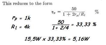
If you do the 150k to the B+ there is an extra resistor+capacitor needed for feedback.In Post #23 I see two gross errors in the schematic. The 150K FB resistor needs to go P-P. The screen of the driver then needs a source of B+. 4.5W of audio when the power tube dissipates only 15.5 Watts defies gravity, And the theoretical limits of a Class A triode.
Better be sure to get a professional to do the proofing on your book before publication.
And with an S=5mA/V of the EF95 the feedback to the cathode is rather small.
There is no problem with gravity here. The Rp of the EL36 triode is less then 1kΩ and I suspect a OPT of 4kΩ. So, accoding to the formula you showed 5W out is possible.
Mona
Attachments
That is not true , as in your "example" G2 is at +115V fixed Voltage and the feedback goes just to the cathode .It is there to provide feedback from the output tube's plate to the cathode's driver. Another example here https://www.diyaudio.com/community/threads/output-tube-plate-to-driver-cathode-feedback.356952/
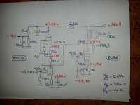
EF95/6AK5 pentode driver stage operation point of the schematic shown above. Don´t underestimate these sh*tty & cheap RF and IF strip tubes, although you most likely will have to select them for microphony. Another interesting candidate is EF80 / 6BX6, used in gazillions of European TV and radio IF strips.

I linked that example to show the plate to cathode feedback principle. At DC both examples are "different", at AC they operate the same. I liked seeing Tom's solution very much, as it cleverly provides the G2 voltage and the feedback with one resistor. (One could also use a resistor from the El36 straight to the driver's cathode and a separate resistor from B+ to G2).That is not true , as in your "example" G2 is at +115V fixed Voltage and the feedback goes just to the cathode .
Above was the question? It is supplied by the anode of the output tube so that the swing at the output tube's plate is sent to the driver's cathode, for feedback.The question remains , why supply the G2 of the input tube from the anode of the output tube ...
OK, I see what that 150K resister is doing now. The FB factor looks like 0.001 if the cathode impedance of the EL95 is ignored.
Plugging that into the formula for NFB I got a gain reduction from 225 to 184, 1.76 db.
That reduces the internal impedance at the plate connexion to the OPT primary, an advantage.
But it also makes the output stage more susceptible to power supply hum & noise.
The same degree of NFB from the secondary would improve both those problems to a degree.
I've used up to 20 db NFB on FB pairs such as this with no stability problems at all.
Even where the OP stage is a pentode & the OPT a replacement type.
Seely's power output formula assumes better than 5% distortion for the triode SE power amp.
Looking at the very long loadline in the 'poor man's 300B' we can see a large difference in the grid spacing
at the extremes, a sure sign of distortion.
I start from the premise that the television tubes allow an excess of dissipated power without affecting them too much so i set a working point over the dissipation hyperbola with 8w situation in which i managed to get 8w with1% THD and only at 9,4w the distortions suddenly increase. It probably be useful to simulate this scheme for which i think the data is sufficient. My experience with these tubes makes me belive that they last a few years in operation and are very cheap anyway
Attachments
I am planning to build an el 36 se amp. Your amp looks great. Found a couple of schematics on the internett. Is it this one you have built your amp after? https://www.diyaudio.com/community/threads/pl36-triode-se.276028/page-2Hi ToddD,
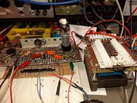
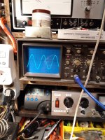
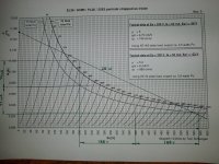
sure this amp was built - I use it almost daily. Regarding the Zobel, please have a look at the plots. The book is still under work, about 700 pages done and still growing. Sorry for the short answer, I have to get some sleep.
Regards, Tom
View attachment 1025530 View attachment 1025531 View attachment 1025532 View attachment 1025528 View attachment 1025529
Hi,I start from the premise that the television tubes allow an excess of dissipated power without affecting them too much so i set a working point over the dissipation hyperbola with 8w situation in which i managed to get 8w with1% THD and only at 9,4w the distortions suddenly increase. It probably be useful to simulate this scheme for which i think the data is sufficient. My experience with these tubes makes me belive that they last a few years in operation and are very cheap anyway
this looks promising, thanks for sharing!
Peter
Hi Peter,because I have an OT with multiple sockets in the secondary and primary I can accurately determine the impendance of the optimal OT depending on the static point of operation of the tube so for the variant tested by me it resulted 4 Kohm . The Schade type reaction is very useful but I recommend using ARTA software for optimizationpopa marius:
Your findings are in line with my experience, EL/PL 36 can take some abuse. What is the primary impedance of the output transformer you are using?
I will try the feedback scheme (Anode of PL36 to G2 of EL183) in my amplifier.
Happy New Year!
Peter
HAPPY NEW YEAR !!
- Home
- Amplifiers
- Tubes / Valves
- PL36 (triode) SE