PL504, PL36P, PL509 tubes can be suprisingly linear and can allow a higher power load than those given in a catalog, with a rigorus selection of PL504 tubes we have made an SE that can cut 8w without NFB at 1% THD of that i think the PL36 can come close to this performance, in fact right i'm ar amplifier with a configuration similar to the Silbatone RI-25 amplifier
What is the application for the pL509?PL504, PL36P, PL509 tubes can be suprisingly linear and can allow a higher power load than those given in a catalog, with a rigorus selection of PL504 tubes we have made an SE that can cut 8w without NFB at 1% THD of that i think the PL36 can come close to this performance, in fact right i'm ar amplifier with a configuration similar to the Silbatone RI-25 amplifier
I have some EL509/6KG6 tubes.
Thanks
With the numbers of TS (bias = -52 V / voltage between cathode and plate = 340 V) the PL36 would be passing about 90 mA, so would be dissipating a little over 30 Watt. I know the PL36 can take some abuse (like many other sweep tubes do) but 30 Watt is about twice the published maximum value. I would be surprised if a PL36 could stand this for longer periods.
I don't see any reason to this. Can you clarify what means "less effective" in this case ?Yea , the transformer phase shift is eliminated but the feedback is ( much) less effective
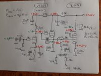
An amplifier similar to the one made by PIEROH tested on a test board and it should be shown that in the case of TV tubes used as triodes the power dissipated is a sum Pa+Pg2 and can be surpisingly high. I have an SE amplifier with the PL504 tube and after three years the wear of the tubes although the power dissipated is higher than the one given in the catalog. If you want you can present the ARTA measurements in this case from 4w to 11wAre you referring to the circuit at post #23 ? There the plate voltage is 298 V and cathode current 52 mA.
The tube is dissipating 15.5 W.
Attachments
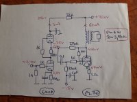

In Post #49 the cct on the left hand side, the 270K FB resister will not do much, it is feeding back into the low impedance of the mu follower. And the theoretical power out from a Class A power triode is 25% of the plate watts dissipated. Check it out in any text covering vacuum tube technology.
Which begs the question, how much of the measured 6W is distortion? And how were the noted measurements made & with what equipment?
Which begs the question, how much of the measured 6W is distortion? And how were the noted measurements made & with what equipment?
There is an interesting page with lots of discussion on using the EL36 for SE here, including some experiments by John Hunter ...
6CM5 / EL36: Applications in Audio
6CM5 / EL36: Applications in Audio
... I tried three topologies: conventional pentode with drive to the control grid, pentode with drive to the screen grid, and triode. The conventional pentode connection was the worst! I couldn't really get good linearity with decent output power. Screen grid drive was a lot better, even though about 42Vpp was required to drive it. ...
... The best was triode connected. ... So, yes it can be done, but it's terribly inefficient when you consider that the heater current is 1.2A (6.3V @ 1.2A = 7.5W heater power alone, for 2.25W useful audio output!). A 6AQ5 or 6V6 will give nearly double the output power for less than half the heater current! I have seen a $3000 amplifier made in Western Australia using a colour TV line output valve (PL509/40KG6). It only gave out 7W! ...
... My latest and successful experiments came from the theory that RC coupling was probably not such a clever idea for screen grid drive. For ordinary control grid drive it's fine as the grid is of infinite impedance. However, screen grids draw current, which does not suit the relatively high impedance of RC coupling. Either transformer or cathode follower drive would have to be used. The practicalities of using an audio transformer meant that a cathode follower stage would be preferred, and so a test circuit was tried.
The results were looking promising but still less than the requisite 4W was forthcoming. At this point the 6CM5 had the screen grid at about 150V and the grid bias set to draw about 45mA anode current. What did become apparent was the less bias the 6CM5 had, the more power it would produce without distortion. So, why not get rid of the grid bias and just control the anode current with the screen grid voltage?
That's where the breakthrough came! With no bias and 25V on the screen, the anode was drawing 45mA at 240V. I couldn't believe it when I was getting 3.8W before clipping into the 15 Ohm load resistor, (and at least 4W into the transformer primary). ...
In Post #23 I see two gross errors in the schematic. The 150K FB resistor needs to go P-P. The screen of the driver then needs a source of B+. 4.5W of audio when the power tube dissipates only 15.5 Watts defies gravity, And the theoretical limits of a Class A triode.
Better be sure to get a professional to do the proofing on your book before publication.
Better be sure to get a professional to do the proofing on your book before publication.
What mystical benefit does the strange connexion of the 150K resister R-GK confer to the circuit? Could that resister not simply be connected to +340V, the EF95 plate supply with the same end result. The RC time constant of 150K & 4.7 microF is such that any signal from the plate of the EL36 above 0.23 Hz goes to common. And R-GK is heated by some of the audio generated by the EL36 output tube.
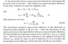
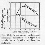
Refer to the attachments, practical Class A SE triode power amps are limited to 25% efficiency when loaded for maximum output. Copied from Samuel Seely, Electron Tube Circuits, McGraw Hill Electrical & Electronic Engineering Series, 1958. During WW2 Seely was on the staff of the MIT Radiation Labs. A book worth having.
Attachments
Tom,Hi ToddD,
sure this amp was built - I use it almost daily. Regarding the Zobel, please have a look at the plots. The book is still under work, about 700 pages done and still growing. Sorry for the short answer, I have to get some sleep.
Regards, Tom
View attachment 1025530 View attachment 1025531 View attachment 1025532 View attachment 1025528 View attachment 1025529
Nice looking amp!
Can you compare this EL36 SE amp vs the EL36 SE amp with the EF184 drivers as a mu follower that you presented at ETF in 2006? I know that has been awhile but wondering if there was a specific reason for changing the driver stage? Any concerns with the EF184 mu follower driver?
thanks
The question remains , why supply the G2 of the input tube from the anode of the output tube ...Post 39 explains Tom's amp.
- Home
- Amplifiers
- Tubes / Valves
- PL36 (triode) SE