lndm said:
I like to bias my 6sn7gt's with led's. I don't want to run them at 8-10mA. I do run them at 3-6mA. I'm considering feeding them the few extra mA from the supply, but this is a little ugly. Is it worthwhile?
You can feed the LEDs from the supply via a CCS. This minimizes injection of supply noise. But the 6SN7 really is happier at 8-10mA.
ryssen said:I use the one with MJE350 at the anode,wouldnt it be the same to remove R2 and use R3 instead?Better to be able to adjust?
No, use both. Adding R2 limits the range of adjustment anf makes it easier to get the correct setting without any risk of smoke.
How is this done,do you mean to make another one just for the Led´s?You can feed the LEDs from the supply via a CCS. This minimizes injection of supply noise.

Ok.No, use both. Adding R2 limits the range of adjustment anf makes it easier to get the correct setting without any risk of smoke.
The first schema with 2 Bc549c whats it for?Just for lower current or?
And the one in the middle can I use it for a 6B4G with the "Cathod resitor?"How,Is it explained somewhere?
Nearly identical questions I asked here http://www.diyaudio.com/forums/showthread.php?postid=899301#post899301


The qualities that you want from a CCS are high output resistance and low output capacitance. For a given design, these are optimised by using the most fragile devices you can get away with. Hence, the 2 x BC549C is great when not much voltage is across the upper device and its power dissipation is low. Once the voltage goes up it tends to push the power dissipation up and that means that BC549C is no longer suitable and MJE340 is required. But a CCS using MJE340 as the upper transistor isn't quite as good as one using BC549C.
In my tweaking progress. I removed the RC filter I had before the CCS,and what I observed is the voltage at the anode
dropped to148v from 170v (6S4) and the B+ got up to 360-365v
So now I have about 300v across the 6B4G little high.Thougt the voltage would be higher at 6S4 with no RC.
But every tweak I have done has bee possitive to the sound,much clearer.So now wich one to test Shoog´s or SY´s,I dont´know.´Then this 300v to the 6B4G could it be lowered with
some CCS at the Cathode"?Apriciate sugestions.
I removed the RC filter I had before the CCS,and what I observed is the voltage at the anodedropped to148v from 170v (6S4) and the B+ got up to 360-365v
So now I have about 300v across the 6B4G
little high.Thougt the voltage would be higher at 6S4 with no RC.But every tweak I have done has bee possitive to the sound,much clearer.So now wich one to test Shoog´s or SY´s,I dont´know.´Then this 300v to the 6B4G could it be lowered with
some CCS at the Cathode"?Apriciate sugestions.
How is this done,do you mean to make another one just for the Led´s?
Exactly. It doesn't have to be a super current source, just an OK current source. One end to the B+, the other to the cathode.
Now, the assumption here is that, universally, lower LED impedance is better. But that may not always be the case, as some intriguing results from rdf in another thread suggest.
I was locking at MPSA92 it can take 300v if I use 2 of them and 2 red Led´s and a trimpot/channel,cheap and nice,would i be alrigt?Or is it enough with one for both chanels Led`s?Exactly. It doesn't have to be a super current source
Can I do this to and use both metods,fun to tweak.My suggested approach has not introduced any noise into my preamp and is considerably simpler than a full CCS.
SY said:the 6SN7 really is happier at 8-10mA.
I set my driver at 10mA, 400V supply and a couple of LED's to bias. From what I can tell so far, they seem made for this. Thanks.
With difficulty. If it was the input stage of a loudspeaker amplifier then you could put a very small resistor below the LED and connect feedback at that point and the amplifier would cheerfully drive the necessarily low impedance feedback network. Alternatively, you could connect a transformer secondary in series with the LED.
Usually, you want one thing or the other. Either a CCS and capacitor coupling to the next stage, or transformer coupling and use the transformer as the anode load. I'm assuming that the LL1660S is happy with DC passing through it.
If I was going to apply global feedback I'd probably use traditional RC in the cathode circuit, but if not, then there's no reason why you shouldn't connect a few red LEDs in series to achieve the correct bias.
If I was going to apply global feedback I'd probably use traditional RC in the cathode circuit, but if not, then there's no reason why you shouldn't connect a few red LEDs in series to achieve the correct bias.

There is an old trick called swamping. With this, you have an unbypassed quantity of cathode/emitter resistance equal to 1/gm. This is the theoretically ideal amount of local feedback and any more bias can/should be in the form of LED's or bypassed resistance.
Theoretically, the normally curved characteristic will be straightened, and any more unbypassed resistance would bend it back the other way.
So, 400 ohms would be a good amount for a 6sn7.
Theoretically, the normally curved characteristic will be straightened, and any more unbypassed resistance would bend it back the other way.
So, 400 ohms would be a good amount for a 6sn7.
Ok.I´m building this CCS with a CCS for the Led´s to have at my driver tube at 15mA.I am goint o have about 495v at the supply,now I wan´t a RC filter how large should the R be?
I, to Led´s should also be 15mA.wait a minute the Leds are serie connected,should that be 30mA???
to have at my driver tube at 15mA.I am goint o have about 495v at the supply,now I wan´t a RC filter how large should the R be? I, to Led´s should also be 15mA.wait a minute the Leds are serie connected,should that be 30mA???
Ryssen said:Ok.I´m building this CCS with a CCS for the Led´s
I, to Led´s should also be 15mA.wait a minute the Leds are serie connected,should that be 30mA???
I think you need to give a diagram to make it absolutely clear what you are proposing.
Ok,lets see if you understand my drawing.
It was the R at the RC filter i wonder what value it should be?
The current trough the tube should be 15mA.And should I set the current trough the Led´s to 15mA or 30mA.Maybe a littke overkill CCS for the Led´s but whata heck,it´s only some Led´s and transitors.

It was the R at the RC filter i wonder what value it should be?
The current trough the tube should be 15mA.And should I set the current trough the Led´s to 15mA or 30mA.Maybe a littke overkill CCS for the Led´s but whata heck,it´s only some Led´s and transitors.
Attachments
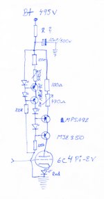
I'm afraid that won't work.
(1) You have 495V. MPSA92 is only rated at 300V
(2) If you draw 15mA through a transistor with nearly 500V across it, it will dissipate 7.5W. MPSA92 is rated at <1W.
(3) If you want to use a CCS for the LEDs that provide the reference for the anode load CCS then you must use an NPN CCS.
(4) The diagram is wrong. Very wrong.
I think you are way out of your depth. Can I suggest that you simplify what you are doing, make it work, then add modifications little by little as your understanding improves. As it is, you will create smoke, waste money, and disappoint yourself. You really need to learn more about theory before embarking on such ambitious schemes.
- Status
- This old topic is closed. If you want to reopen this topic, contact a moderator using the "Report Post" button.
- Home
- Amplifiers
- Tubes / Valves
- Ping Sy: LED for Cathode Bias