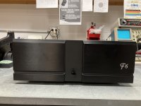
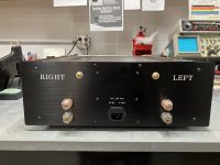
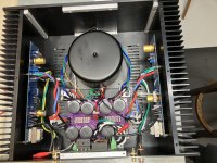
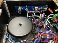
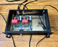
My F6. I'm using the DIYStore F6 PCB's along with R. Thatcher P/S, and rectifiers with snubber PCB's. Mounted on the back panel is Mark Johnson's soft start with low voltage on/off (H9KPXG) with the BIG inrush current limiter. Antek AS-4218 torroid transformer with steel cover.
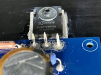
The output devices are SemiSouth SJEP120R063 SiC JFET's, this is an all JFET devices amplifier.
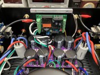
I swapped the zener diodes for blue LED's ( I had to ignore the zener symbol on the PCB for the blue LED's) and set bias to 150mV on Q1 with Q2 = 148.6mV using 0.1 ohm source resistors. The input resistors are Vishay Z-Foil naked resistors I had in stock and Audio Note gold capacitors. Nelson stipulated a 100 ohm 5W resistor for the feedback resistor, so I used MOX 100 ohm 5w.
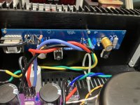
The left channel board is stable as a rock for bias and offset, the right channel has the bias stable, however, the offset varies from 1.2mV to 44mV in 5 minutes. I keep adjusting the offset back to close to zero, however it continues to vary. I wonder if I need to increase the gate resistors to a value greater than the 47 ohm specified?
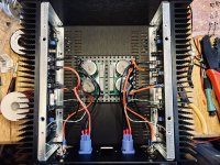
I need to clean some rosin dust off the boards and hook up the front panel LED after I find the brightness I prefer.
I'll power it up for a few hours and see what happens to the offset on the right channel.
The output devices are SemiSouth SJEP120R063 SiC JFET's, this is an all JFET devices amplifier.
I swapped the zener diodes for blue LED's ( I had to ignore the zener symbol on the PCB for the blue LED's) and set bias to 150mV on Q1 with Q2 = 148.6mV using 0.1 ohm source resistors. The input resistors are Vishay Z-Foil naked resistors I had in stock and Audio Note gold capacitors. Nelson stipulated a 100 ohm 5W resistor for the feedback resistor, so I used MOX 100 ohm 5w.
The left channel board is stable as a rock for bias and offset, the right channel has the bias stable, however, the offset varies from 1.2mV to 44mV in 5 minutes. I keep adjusting the offset back to close to zero, however it continues to vary. I wonder if I need to increase the gate resistors to a value greater than the 47 ohm specified?
I need to clean some rosin dust off the boards and hook up the front panel LED after I find the brightness I prefer.
I'll power it up for a few hours and see what happens to the offset on the right channel.
Attachments

I wonder if I need to increase the gate resistors to a value greater than the 47 ohm specified?
hop to 150R
150, 160, 180 - whatever you have in drawer
I had 150 or 221, so I used the 150's, everything stable, bias at 150mV and offset below 2mV.
I'm going to let it run for today and then hook up a dummy load and check the distortion characteristics using REW this weekend. I'll be sure to post the results.
Once again, thanks for your help.

For a while I’ve I had these B1ish boards built by another forum member. So I wired and cased them up, and they work! No anomalies or noise, and they sound great.
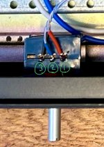
One greenhorn issue, though. I wired the ALPS pot backwards.
If the pot is providing maximum attenuation fully clockwise, which of the pin connections should I swap?
One greenhorn issue, though. I wired the ALPS pot backwards.
If the pot is providing maximum attenuation fully clockwise, which of the pin connections should I swap?
Attachments

Amp Camp Amp (my third). Chassis is acacia wood, aluminum, and mirrored acrylic. Circuit is dead bug style point-to-point wiring. One-way mirror reveals an homage to the esteemed Mr. Pass. More deets here: ACAConcept III.


- Home
- Amplifiers
- Pass Labs
- Pictures of your diy Pass amplifier