Thanks all for positive reply")
Siberia: All metall milling are done by me = manuell handling, no CNC milling.
I have have made all drawing in CAD before milling. (Solid Works).
myleftear: RG174, actually, maybe to the UV-pcb, but from the XLR/RCA connectors I use SUPRA EFF-I to main pcb.
Siberia: All metall milling are done by me = manuell handling, no CNC milling.
I have have made all drawing in CAD before milling. (Solid Works).
myleftear: RG174, actually, maybe to the UV-pcb, but from the XLR/RCA connectors I use SUPRA EFF-I to main pcb.
Wow, I'm deeply impressed!Hi,
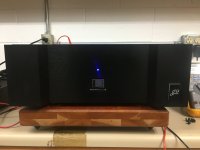
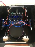
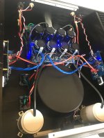
Almost finish with my Aleph 1.2
I started the projekt 13 years ago! Now I only have to power them up for the very first time, but i'm not in a hurry.
They messured L680xW480xH400mm and the weight about 65kg.
I have Pass design i mind when I made the front, its made of 20+25mm aluminium plates, just for design.
kk-pcb.net and sjostromaudio.com have delivered the pcb's, other ones are DIY like VU-meter pcb, DC protection, T-toggle for switch.
The cooling fins from heatsinkusa.com, and I choose the 10.080" 16 inch tall x 10pcs. I split two of them so each side are made of 2½pc.
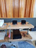
The picture with the set up contains a look a like HPA-1, but is also made by me with Whammy inlet. Comming up soon
The speakers are mostly Dynaudio element and the front speaker are the Dynaudio model "Finale" but with upgraded element.
Missing in the set up are my Aleph 1.7 who are almost finnished on the building table. (Sorry for misspelled).
I hope you will enjoy the pics below.
Best regards, Mikael from Sweden.
View attachment 1152668 View attachment 1152669 View attachment 1152670 View attachment 1152671 View attachment 1152672
Hi,
Almost finish with my Aleph 1.2
I started the projekt 13 years ago! Now I only have to power them up for the very first time, but i'm not in a hurry.
They messured L680xW480xH400mm and the weight about 65kg.
I have Pass design i mind when I made the front, its made of 20+25mm aluminium plates, just for design.
kk-pcb.net and sjostromaudio.com have delivered the pcb's, other ones are DIY like VU-meter pcb, DC protection, T-toggle for switch.
The cooling fins from heatsinkusa.com, and I choose the 10.080" 16 inch tall x 10pcs. I split two of them so each side are made of 2½pc.
The picture with the set up contains a look a like HPA-1, but is also made by me with Whammy inlet. Comming up soon
The speakers are mostly Dynaudio element and the front speaker are the Dynaudio model "Finale" but with upgraded element.
Missing in the set up are my Aleph 1.7 who are almost finnished on the building table. (Sorry for misspelled).
I hope you will enjoy the pics below.
Best regards, Mikael from Sweden.
Fugly!

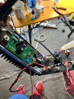
that copper plates look very nice - how much are their thicknessMost of the part were designed with 3D computer modeling, that I can simulate the assembly of all part and then put on cnc cut. More pictures of that part.
Happy to see you guy enjoying.
would you please recommend a properly grade of copper to use as a copper plate connecting power supply filtering caps In amp
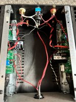
Pictures of my J2 clone by EUVL, SJEP120R100's compliments of Nelson Pass during codyt's first give away. Notice the snubber PCB's on each diode bridge. One channel has 1.2 - 0.2mV and the other 2.6 - 3.2mV of DC offset. I changed RV1 from 100 ohm 1 turn to a 25 turn pot. made a very big difference setting DC offset.
Attachments
markw51:Each channel has its own rectifier and filter bank - two filter banks on the same board. View attachment 1158392 Only the ground is common.
I am certainly no expert, but I am surprised by the value of the resistors in your power supply. The "R" in my CRC power supplies is typically 0.07R to 0.15R, so your value of 1175R seems very high to me. Can you explain the rationale?
Regards,
Scott
markw51:
I am certainly no expert, but I am surprised by the value of the resistors in your power supply. The "R" in my CRC power supplies is typically 0.07R to 0.15R, so your value of 1175R seems very high to me. Can you explain the rationale?
Regards,
Scott
Probably a typo, perhaps 0.47R x 4.
If 2A of current, 1175R would be dissipating 4.7kW!
I just pulled my Sony VFET P channel amp out of rotation and the J2 clone replaced it. I'll let you know after the weekend when I've had time to compare. I'm using the same preamp, just with the balanced outputs going to the J2.That's a very handsome amplifier -- kudos! How does it sound?
They are 0.47 ohm resistors in parallel. The writing on the side of these military grade components can be confusing.markw51:
I am certainly no expert, but I am surprised by the value of the resistors in your power supply. The "R" in my CRC power supplies is typically 0.07R to 0.15R, so your value of 1175R seems very high to me. Can you explain the rationale?
Regards,
Scott
They are 1 mm thk. just a non alloy copperthat copper plates look very nice - how much are their thickness
would you please recommend a properly grade of copper to use as a copper plate connecting power supply filtering caps In amp
- Home
- Amplifiers
- Pass Labs
- Pictures of your diy Pass amplifier