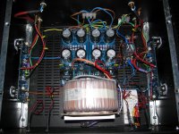
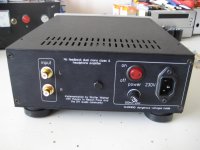
Power supply is pretty safe to touch as it is only around 30V, of course 60V across +/-, but still within safe limits ")
Rectifiers are also pretty far back, but I have thought about what happens if you drop your key over them. It has a total of 8 properly sized fuses though
Thank you ALL for your KIND comments!
Kiitos!
Rectifiers are also pretty far back, but I have thought about what happens if you drop your key over them. It has a total of 8 properly sized fuses though
Thank you ALL for your KIND comments!
Kiitos!


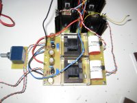
Another vanilla F5.
Nothing like the monster builds others show but I am pleased with it.
V3 boards from the shop.
LEDs brought to front panel.
Relay for switching on mains power.
Nothing like the monster builds others show but I am pleased with it.
V3 boards from the shop.
LEDs brought to front panel.
Relay for switching on mains power.
Attachments
Last edited:
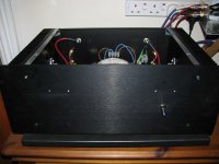
Work in progress! 600VA 24V AC transformer, 216000uF power supply.
An externally hosted image should be here but it was not working when we last tested it.
500VA, CLC supply with Hammond chokes. Lovely amp.
Hi
Where did you buy the case ?
Thanks
Nice chassis, is this one from Breeze audio
I am planning to use it for M2.
Actually they can drill according to your files as well, the only problem is high cost of transportation as they use expensive methods, but hence delivered really fast.
I am planning to use it for M2.
Actually they can drill according to your files as well, the only problem is high cost of transportation as they use expensive methods, but hence delivered really fast.
Last edited:
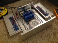
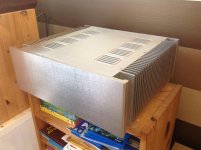
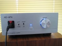
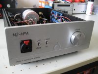
M2 Headamp finally ready
 It took me some months to finish, but finally it's as intended in a nice chassis.
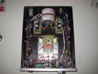
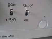
It's a dual mono headphone amp, with the M2 gain stage, with the Diyaudio headphone amp output stage with the Jung/Didden Super regulator boards and not to forget the crossfeed circuit from EUVL from his F5-HA Description V1.4 document.
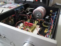
It was a nice journey back in time, to make my own PCB's, with all the chemicals and so on
Lessons learned: design one big PCB with everything on it, connecting all those little PCbs is a lot of work It will look neater also.
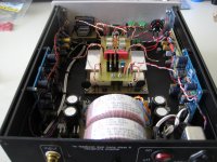
The Edcor's did pick up a lot of hum from the initially placed R-core transformer. Changing to toroid's and placing them this way, solved the hum problem.
The outputstage has 3.3 Ohm source resistors, resulting in a 180mA bias at 15.0 Volts. Enough to drive every headphone, I guess.
Regulators and output stage generate about 10 Watts of heat each channel which can be easily dissipated by the side panels.
Resulting in a warm, 42 degrees Celsius amplifier chassis...
With the crossfeed and relais switch board, I can select to listen to only the outputstage, outputstage with M2 gain and outputstage with M2 gain and crossfeed.
Off course it sounds very, very nice!
Walter
It took me some months to finish, but finally it's as intended in a nice chassis.It's a dual mono headphone amp, with the M2 gain stage, with the Diyaudio headphone amp output stage with the Jung/Didden Super regulator boards and not to forget the crossfeed circuit from EUVL from his F5-HA Description V1.4 document.
It was a nice journey back in time, to make my own PCB's, with all the chemicals and so on
Lessons learned: design one big PCB with everything on it, connecting all those little PCbs is a lot of work
It will look neater also.The Edcor's did pick up a lot of hum from the initially placed R-core transformer. Changing to toroid's and placing them this way, solved the hum problem.
The outputstage has 3.3 Ohm source resistors, resulting in a 180mA bias at 15.0 Volts. Enough to drive every headphone, I guess.
Regulators and output stage generate about 10 Watts of heat each channel which can be easily dissipated by the side panels.
Resulting in a warm, 42 degrees Celsius amplifier chassis...
With the crossfeed and relais switch board, I can select to listen to only the outputstage, outputstage with M2 gain and outputstage with M2 gain and crossfeed.
Off course it sounds very, very nice!
Walter
Attachments
-
 IMG_5957ww.jpg231.2 KB · Views: 645
 -
 IMG_5948ww.jpg345.7 KB · Views: 612
 -
 IMG_5945ww.jpg335.9 KB · Views: 573
 -
 IMG_5938ww.jpg351.3 KB · Views: 627
 -
 IMG_5933ww.jpg266.5 KB · Views: 1,337
 -
 IMG_5930ww.jpg255.9 KB · Views: 1,386
 -
 IMG_5929ww.jpg320 KB · Views: 1,404
 -
 IMG_5906ww.jpg350.7 KB · Views: 1,447
 -
 IMG_5900ww.jpg315.9 KB · Views: 1,542
It took me some months to finish, but finally it's as intended...
It was a nice journey back in time, to make my own PCB's, with all the chemicals and so on
Lessons learned: design one big PCB with everything on it, connecting all those little PCbs is a lot of work
Off course it sounds very, very nice!
Walter
Walter thanks you are incredible talented i admire that super well made diy Hamp

Special congratulations for your self home made boards


- Home
- Amplifiers
- Pass Labs
- Pictures of your diy Pass amplifier