I like the first watt, you could even do PassdiyOne last round of amateur graphic design...I did one with the FW logo that was suggested earlier by bcmbob. If I did decide to do the engraving I would do one of these two. However, it's possible I might not choose the F5 to be under the hood for good so maybe just printing it out on a plastic cling sheet would be best. Hell, I could just make sticky cling sheets for each Pass diy amp circuit.
You could do a bunch for each amp circuit on dark Plexiglas (backside painted black and etched), and add a little back lighting. Then you can match the logo to your mood. Some acorn nuts or other special hardware might look nice.
Some acorn nuts or other special hardware might look nice.Attachments
Last edited:
You could do a bunch for each amp circuit on dark Plexiglas (backside painted black and etched), and add a little back lighting. Then you can match the logo to your mood.
Do you mean something like that?
http://img.alibaba.com/photo/514636510/acrylic_LED_signboard_plexiglass_billboard_for_bar.jpg
Could be amazing, cut out an square on the front metal panel, then engrave your plexi sheet with a CNC or whatever and then screw it from the inside so you can make your plexi piece a bit larger than the cutted out square so the edges will look fine.
Heatsinks max out around 58 C with 0,225A per rail bias and the MOSFETs are around 62 C.
Can't use 2.5 A bias per rail since my T ambient is around 25C this time of year
I also implemented a thermal protection by glueing 75C switches on the Toshibas.
Didn't need too implement C3 and C4 for stability.
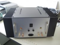
Congratulations Walter. Fantastic build quality.
Are you using the cascode transistors? Is there provision on the Tea-bag boards for these and for C3 and C4?
At your bias settings wont the voltage that the diodes see be too low for them to kick in?
About how much does your amp weigh in at?
Thanks again for sharing.
Can't use 2.5 A bias per rail since my T ambient is around 25C this time of year
I also implemented a thermal protection by glueing 75C switches on the Toshibas.
Didn't need too implement C3 and C4 for stability.
Congratulations Walter. Fantastic build quality.
Are you using the cascode transistors? Is there provision on the Tea-bag boards for these and for C3 and C4?
At your bias settings wont the voltage that the diodes see be too low for them to kick in?
About how much does your amp weigh in at?
Thanks again for sharing.
Heatsinks max out around 58 C with 0,225A per rail bias and the MOSFETs are around 62 C.
Can't use 2.5 A bias per rail since my T ambient is around 25C this time of year
I also implemented a thermal protection by glueing 75C switches on the Toshibas.
Didn't need too implement C3 and C4 for stability.
Congratulations Walter. Fantastic build quality.
Are you using the cascode transistors? Is there provision on the Tea-bag boards for these and for C3 and C4?
At your bias settings wont the voltage that the diodes see be too low for them to kick in?
About how much does your amp weigh in at?
Thanks again for sharing.
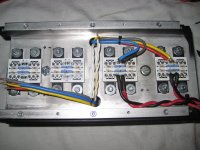
Yes, I use the exact cascode transistors Pa specified, they were the only ones easy to get
They are provided on the Teabag boards just as C3 and C4. The board follows the exact schematic of the version 3.The diodes will kick in when there is a big current needed for the speakers so around 0.4 volt over 0.235 Ohm is around 1.7 Amp or more.
I use 4 Ohm speakers.
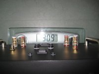
This is the weight:
Attachments
Last edited:
Haha, it's just because I didn't have room for them.
But it gives no problems, I have no hum at all.
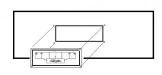
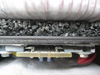
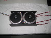
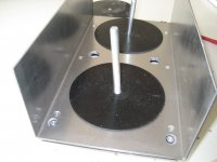
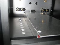
But as you can see on the pictures I have made a shielding sub-chassis for the trafos. It is not, as the rest of the case of aluminum, but made of steel plate 2mm thick.
So the input section doesn't see the trafos.
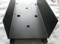
The sub chassis with the trafos and rectifier diodes can be removed separately from the case and also prevents bending the bottom plate from the weight of the trafos.
Walter
Walter, have you isolated the sub chassis from the chassis bottom plate with rubber feet? I have looked hard but don't see the rectifiers anywhere. I see your logic in keeping output wires and wires from the PSU to the board as short as possible. What AWG wire did you use? Any chance you can post an additional picture showing the rectifiers? Thanks.
Walter, have you isolated the sub chassis from the chassis bottom plate with rubber feet? I have looked hard but don't see the rectifiers anywhere. I see your logic in keeping output wires and wires from the PSU to the board as short as possible. What AWG wire did you use? Any chance you can post an additional picture showing the rectifiers? Thanks.
Hi nashbap,
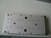
Here are more pictures during building process... it will give you an impression how it evolved.
First I wanted it, to just hold the transformers, and hide the'' noisy' rectifiers.
Later on there was some discussion on DIYaudio if the diodes wouldn't become too hot. So the U-shape metal would bring some extra coolness and also shielding for the transformers.
The rectifiers are not getting hot, by the way... the output MOSFET's are the ones, producing all the heat
It would have been nicer to also isolate the whole sub-chassis with rubber feet, but I didn't do that.
Walter
Attachments
Last edited:

extremely Fugly!
I hope you're having that funnyrubbery thing also between Donut and it's covering bell/plate
Thanks ZM, I know what you mean, but there is still not such a ring..
It's on my to do list....
But the massive output wires won't move by their selves, I hope....
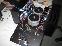
So it looks like the rectifiers are in a tray under the two transformers. Right?
What was your reasoning behind using 25V secondary output transformers and not higher, maybe around 34V?
Where did you buy the Toshiba Mosfets and the Jfets from? I read a post from Tea-Bag mentioning "The FQP variants (FQP19N20C and FQP12P20) are still available via distribution" Did you consider them?
That's a tremendous amount of fantastic machine work you have done!
Flexibly mounted transformer will vibrate.
How much vibration I don't know.
Solid core copper lead outs will suffer fatigue, if flexed.
How long till they crack, I don't know.
You are building in a design flaw that WILL AFFECT reliability.
Change the leadouts to flexible !!!!!!
How much vibration I don't know.
Solid core copper lead outs will suffer fatigue, if flexed.
How long till they crack, I don't know.
You are building in a design flaw that WILL AFFECT reliability.
Change the leadouts to flexible !!!!!!
WalterW.
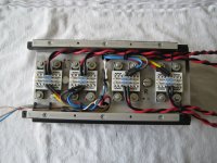
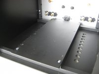
Are the points (blue/white arrows) in this picture soldered with heat shrink, or posts with removable coupling? They are very smooth/uniform and don't look like they are soldered. Looking for a tip for one of my builds.
They are heat shrink tube, they hide the melted, pulled back isolation when you are soldering thick wires
I like to work with shrink tube, gives a nice professional look.I thought soldering will be the best, where high peak currents could be expected...
Walter
Flexibly mounted transformer will vibrate.
How much vibration I don't know.
Solid core copper lead outs will suffer fatigue, if flexed.
How long till they crack, I don't know.
You are building in a design flaw that WILL AFFECT reliability.
Change the leadouts to flexible !!!!!!
The red/black cabling is all flexible 4.0 mm2 cable.
Walter
- Home
- Amplifiers
- Pass Labs
- Pictures of your diy Pass amplifier