Thanks, which resistors are you referring to?
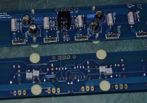
The source resistors are 0.47 Ohm 5W Fukushima Futaba MPC74's which parallels to 0.235 Ohm 10 Watt
Other resistors in the signal path are Dale CMF55's.
Notice that I lowered R5 and R6 from the original design from 1K to 475Ohm for better biasing the Toshibas.
The trafo spec: Amplimo 2 x 625VA 2x25V 2x 12.5 Amp.
So total of 1.25KVA for two channels.
Looking forward to see pictures of your build!
Walter
I am have changed R11 and R12 from 2.2k to 1.2k for the lower Vgs of the Toshiba devices.
I am using the 1R 3W Panasonic source resistors paralleled to form 0R5 as specified on the circuit diagram. Are those MPC74 resistors so much better?
O.K. Just did a Google spreadsheet to collect basic info for a possible group buy for the Keratherm product. It is primarily for North American amp builders, but can also serve as well for others.
I am have changed R11 and R12 from 2.2k to 1.2k for the lower Vgs of the Toshiba devices.
I am using the 1R 3W Panasonic source resistors paralleled to form 0R5 as specified on the circuit diagram. Are those MPC74 resistors so much better?
R11 and R12 from 2.2k to 1.2K = for better thermal tracking.
Those resistors are in series with the NTC, so a lower value means the NTC has more influence on the circuit.
R5 and R6 from 1K to 475 Ohm = for the lower Vgs, biasing the Toshibas.
The 3W Panasonics will be excellent too, if Nelson Pass uses them in his Pass Labs amps then it's good enough for me also!
Hi Walter
I see you have the transformers at the middle of the case.
As i know it is recommend to be with the trafos so far as possible away from the input stage.
Are the any problems with your trafo arrangement? or what is to consider
to place the trafos this way?
Because i also have to put two big trafos in my case. And this way i could it do it the easy way.
My first thought was to place them in the front of the case and stack them
but this is a little bit unfunctional.
thanks alex
Hi Walter
I see you have the transformers at the middle of the case.
As i know it is recommend to be with the trafos so far as possible away from the input stage.
Are the any problems with your trafo arrangement? or what is to consider
to place the trafos this way?
Because i also have to put two big trafos in my case. And this way i could it do it the easy way.
My first thought was to place them in the front of the case and stack them
but this is a little bit unfunctional.
thanks alex
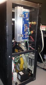
Haha, it's just because I didn't have room for them.

But it gives no problems, I have no hum at all.
But as you can see on the pictures I have made a shielding sub-chassis for the trafos. It is not, as the rest of the case of aluminum, but made of steel plate 2mm thick.
So the input section doesn't see the trafos.
The sub chassis with the trafos and rectifier diodes can be removed separately from the case and also prevents bending the bottom plate from the weight of the trafos.
Walter
Walter
I see that you have used 470uF capacitors for C1 and C2, where 10uF was specified in NP's F5T V3 schematic. Any reason you used that value? Is this dependant on the PSU configuration?
That capacitor is just a decoupling cap, and not critical. I used a 'high end' type capacitor, Nichicon Muse.
Somebody at the forum told me that it's nicer to put a quality cap over the big computer grade electrolytic capacitors....
Walter
That capacitor is just a decoupling cap, and not critical. I used a 'high end' type capacitor, Nichicon Muse.
Somebody at the forum told me that it's nicer to put a quality cap over the big computer grade electrolytic capacitors....
Walter
OK, so basically even a 220uF would work in that spot? I thus assume that NP specified 10uF just because 'he had them in stock'.
The local decoupling has a quite different duty from the smoothing capacitors.
High quality decoupling that is specifically selected for that duty is very likely to achieve best performance from the amplifier. That is best measured performance and best sounding performance.
High quality decoupling that is specifically selected for that duty is very likely to achieve best performance from the amplifier. That is best measured performance and best sounding performance.
I like the muse caps AndrewT is very correct in his statement. If the small value muse is as close to the circuit as can be the inductance of the wire or trace will be before it and can be a small help rather than a problem A clc rather than c c l then load. Granted a small inductance but still best placed before the last cap.The local decoupling has a quite different duty from the smoothing capacitors.
High quality decoupling that is specifically selected for that duty is very likely to achieve best performance from the amplifier. That is best measured performance and best sounding performance.
My problem is not with the quality of the decoupling caps to use. There my preference is usually for the Panasonic FC or FM caps because of their better temperature rating than the Muse caps.
However, how does one determine the best possible value for the decoupling cap? Using an oscilloscope on the rails to see which ones filter left over noise after the smoothing and rectification the best? Listening tests, or both? In other words, how does a designer like NP decide which value to use on a specific circuit, as I have seen values from 10uF to 470uF used for this purpose, and sometimes it is bypassed by another 100nF cap also, sometimes not.
However, how does one determine the best possible value for the decoupling cap? Using an oscilloscope on the rails to see which ones filter left over noise after the smoothing and rectification the best? Listening tests, or both? In other words, how does a designer like NP decide which value to use on a specific circuit, as I have seen values from 10uF to 470uF used for this purpose, and sometimes it is bypassed by another 100nF cap also, sometimes not.
The size of the caps will determine the frequency range at witch the caps have the lowest impedance.
The circuit topology determines the sensitivity of the circuit for power supply impedance as a function of frequency. Hence different circuits use different cap values.
Having looked at various NP designs I see the recurring use of standard component values like 10u and 220u caps. Wayne tends to bypass 220u caps in his designs with smaller caps in the signal and power path. NP tends to do that less.
Personally I favour ballanced designs and they have minimal ground currents as well as easy decoupling from rail to rail for signal current.
the electrolytic is NOT BYPASSED......................... I have seen values from 10uF to 470uF used for this purpose, and sometimes it is bypassed by another 100nF cap also, sometimes not.
The HF decoupling is in a different location from the MF decoupling.
These two decoupling types are separated by trace impedance.
Yes Andrew, I understand what you are saying. BYPASSING is the wrong term technically to use. What I refer to is putting a smaller value cap in parallel to the the electrolytic, where each handles a different frequency band if one can put it that way. I was using layman's terminology, sorry for the confusion it caused.
Is heat that large a factor at the location in question. Well there is some data that the higher temp cap will live longer in the same application but for this one I felt not that big a factor.My problem is not with the quality of the decoupling caps to use. There my preference is usually for the Panasonic FC or FM caps because of their better temperature rating than the Muse caps.
However, how does one determine the best possible value for the decoupling cap? Using an oscilloscope on the rails to see which ones filter left over noise after the smoothing and rectification the best? Listening tests, or both? In other words, how does a designer like NP decide which value to use on a specific circuit, as I have seen values from 10uF to 470uF used for this purpose, and sometimes it is bypassed by another 100nF cap also, sometimes not.
It might hurt a litlle or a lot.I actually did use "Bypass Caps" on my 220uF decoupling caps.
I used 220uF Panny FM's and each one got a Vishay 1837 .01uf.
I don't know what difference it makes but I figured it couldn't hurt.
You should test the supply rails for ripple or oscillation when subjected to reasonable step changing loadings.
Haha, it's just because I didn't have room for them.
But it gives no problems, I have no hum at all.
But as you can see on the pictures I have made a shielding sub-chassis for the trafos. It is not, as the rest of the case of aluminum, but made of steel plate 2mm thick.
So the input section doesn't see the trafos.
The sub chassis with the trafos and rectifier diodes can be removed separately from the case and also prevents bending the bottom plate from the weight of the trafos.
Walter
Thank you
Same problem in my case not so much room for the trafos.
I will think about this solution... maybe i give it a try
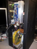
As promised, here is a link to the progress made on the liquid cooling project.
Attachments
One last round of amateur graphic design...I did one with the FW logo that was suggested earlier by bcmbob. If I did decide to do the engraving I would do one of these two. However, it's possible I might not choose the F5 to be under the hood for good so maybe just printing it out on a plastic cling sheet would be best. Hell, I could just make sticky cling sheets for each Pass diy amp circuit.
Attachments
- Home
- Amplifiers
- Pass Labs
- Pictures of your diy Pass amplifier