I actually ordered a couple more yesterday.I might get myself a couple of these for bench testing given their flexibility.
View attachment 1047510
View attachment 1047511
Current project - late 1950s phillips receiver + record deck.
That receiver seems to be in a decent shape for the age. I'd love to do something like that, I keep looking at vintage radios on e-bay and gumtree, but not enough time to dedicate at the moment.
Hi jcalvarez,The inverter is from Aliexpress, bought it after noticing that @kodabmx used it in one of his amps:
https://www.aliexpress.com/item/32688618917.html?spm=a2g0o.productlist.0.0.1d364a12fPnUpq&algo_pvid=ebf3e158-aea8-4bce-94a8-40a4366f7f54&algo_exp_id=ebf3e158-aea8-4bce-94a8-40a4366f7f54-0&pdp_ext_f={"sku_id":"60468402583"}&pdp_pi=-1;8.55;-1;-1@salePrice;GBP;search-mainSearch
Looks like this:
View attachment 1043696
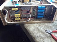
I can only vouch that this one works. I previously ordered a slightly different one, had silver heatsinks and no rectified output, and it died after 15 min of being lightly loaded. This one works quite well, gives a square rectified or AC outputs, 110/200/220/280, I used it with a doubler, just two 22uf caps connected to the output and the middle to one of the AC taps.
I measured again to be sure, and is around 525V @220mA, 560V @90mA.
As is the case with many boards from Aliexpress, your mileage may vary. I have tested the combination for around 3 hours, loaded at 220mA, so far so good. Difficult to get a better value for £8.55 inc delivery. I paid ~£130 for a Hammond 372JX a while ago. The whole setup here, including the 12V 150W SMPS is less than £20.
I am very interested in this DC to AC converter. However, I have no knowledge of this kind of circuit. Can you help me understand the differences between AC and DC output on the board?
Specifically, if I just want a 280V DC supply, should I just connect the DC- to the ground and connect DC+ to conventional CLC or CRC filtering circuits?
Are there any suggestions on what you think will be needed for a 150 mA demand for a small single ended amplifier? I assume we don't need large chokes and capacitors as the switching frequency is quite high.
In your case, you use the AC taps for a voltage doubler. By the descriptions you said, I assume you do not use any rectifier diodes in the attached schematic. If this is true, I wonder why do we need rectifiers for voltage doubler in tube amplifiers. Can you please show me the schematic of you voltage doubler and filtering circuits? Thanks.
Attachments
Hi Mercury99,Hi jcalvarez,
I am very interested in this DC to AC converter. However, I have no knowledge of this kind of circuit. Can you help me understand the differences between AC and DC output on the board?
Specifically, if I just want a 280V DC supply, should I just connect the DC- to the ground and connect DC+ to conventional CLC or CRC filtering circuits?
Are there any suggestions on what you think will be needed for a 150 mA demand for a small single ended amplifier? I assume we don't need large chokes and capacitors as the switching frequency is quite high.
In your case, you use the AC taps for a voltage doubler. By the descriptions you said, I assume you do not use any rectifier diodes in the attached schematic. If this is true, I wonder why do we need rectifiers for voltage doubler in tube amplifiers. Can you please show me the schematic of you voltage doubler and filtering circuits? Thanks.
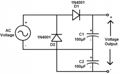
There are 2 options: using the bridge that cames with the board, or using your own. I use the diodes that comewith the board. The attached picture shows the output stage of the DC-AC converter. If there are other questions you can switch to a new thread or PM me to avoid polluting this thread.
Last edited:
EF6 driver, EL3N SE
Hi,
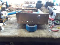
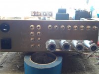
Just finished. New look (this time no "box") thanks to a friend of mine.
It is an EL3N Single Ended with a EF6 triode connected driver. PSU and amplifier on separate chassis. Chassis both plywood, no metal parts used. Earth/ground consists of a 1mm2 silver wire..
Sound is very much okay. I tried both EL3N connected in triode and pentode (1.3W vs 4.5W) and do not understand why some people dislike pentode connection.. ;-)
Was a battle to get the parts in the small space.. but managed..
Hi,
Can you share the schematic if you don't mind ?
I'm building EL3nSE with EF6, (EL3n UL connection.)
Thank you.
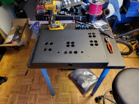
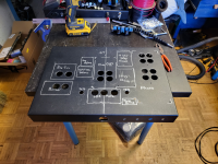
Here begins another preamp. The box helps catch the filings from the drilling.
Fun fact: The HEIC file I took was 2MB. The PNG that was exported and uploaded here was 12.1MB, the forum resized it to 4.3MB. Still over twice the size of the original.
Fun fact: The HEIC file I took was 2MB. The PNG that was exported and uploaded here was 12.1MB, the forum resized it to 4.3MB. Still over twice the size of the original.
Attachments
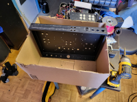
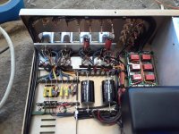
That looks very high tech (and big!) for a preamp. What's the function? Phono, mic, line?Here begins another preamp. The box helps catch the filings from the drilling.
Fun fact: The HEIC file I took was 2MB. The PNG that was exported and uploaded here was 12.1MB, the forum resized it to 4.3MB. Still over twice the size of the original.
Phono, line, buffer for xfmr coupled output, gain for eq input, bluetooth, 6e2 level meter, in-13 level meter, relay input switcher, 4 in, 4 analog variable out, 1 variable buffered xfmr out, 1 variable optical/coax out, 1 direct input, 1 direct line out, 1 attenuated line out. I don't think I forgot anything ") PSU is separate and built already (ATX powering DC-DC boost into linear regulators).
PSU is separate and built already (ATX powering DC-DC boost into linear regulators).
PSU is separate and built already (ATX powering DC-DC boost into linear regulators).Surely you can't play Crisis on itPhono, line, buffer for xfmr coupled output, gain for eq input, bluetooth, 6e2 level meter, in-13 level meter, relay input switcher, 4 in, 4 analog variable out, 1 variable buffered xfmr out, 1 variable optical/coax out, 1 direct input, 1 direct line out, 1 attenuated line out. I don't think I forgot anything
PS Sorry, could not resist.
Wow! Another work of art!Here's another 6AS7G OTL headphone amp I built for a friend on Head-Fi forum. Back panel has a three-position toggle switch for amp and two pairs of RCA pass throughs. Chassis machined and coated by Dave at Landfall Systems.
View attachment 1050736
View attachment 1050735
View attachment 1050733
View attachment 1050734
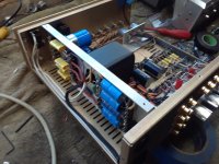
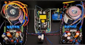
I recently got the itch and built another preamp which oddly enough I had the parts for laying around.
Due to it being the eighth one I've built on this design I tend to order lots of parts and have them stashed everywhere...
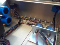
I've still got to wire the cinemag transformers on the moving coil phono input, but the rest should work...
Due to it being the eighth one I've built on this design I tend to order lots of parts and have them stashed everywhere...
I've still got to wire the cinemag transformers on the moving coil phono input, but the rest should work...
Attachments
Yes I had one wire misplaced las tonight when I powered it up.Nice layout, you can tell you've done this before, do still have to de-bug on the first few power up's?
Should be easy to spot in the photos.
I was pulling signal from the feedback connection at the cathode instead of the capacitor next to it attached to plate.
Simple mistake really.
Hard part is getting that relay board built correctly with no opens, shorts,or cross talk.
It puts out a clean sine wave on every channel and every right input spits out on the right output, same with the left.
No I'm not perfect but the mistakes are easily corrected.
Very interesting, it's the first time I see the tubes coming out of the back and horizontally. Great build!I recently got the itch and built another preamp which oddly enough I had the parts for laying around.
Due to it being the eighth one I've built on this design I tend to order lots of parts and have them stashed everywhere...
I've still got to wire the cinemag transformers on the moving coil phono input, but the rest should work...
That is quite something- designing in 3 dimensionsVery interesting, it's the first time I see the tubes coming out of the back and horizontally. Great build!
I think I got that one too, 300V 12V 6V?The latest "Little Miracle" amp using a Sh*tty but functioning PSU.
- Home
- Amplifiers
- Tubes / Valves
- Photo Gallery