Very well done!
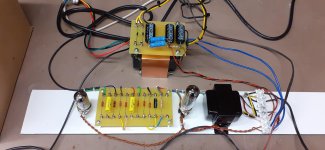
Logical- one can see the schematic by looking at the photo of your circuit.
But we do not know which tubes are used. Moreover, how is the filament supply done. No hum? Do not detect how this is done except from those brown twisted leads.
"But we do not know which tubes are used. Moreover, how is the filament supply done. No hum? Do not detect how this is done except from those brown twisted leads."
You can determine all this from one photo of all the other amps shown in the photo gallery?
Sorry I do not quite understand what you by "You can determine all this from one photo of all the other amps shown in the photo gallery?"
You have to help me here : where are those photos?
Thanks.
Should be a good amp/speaker combo.Just finished my first DIY audio project. The ST120 is beautiful and sounds great on my klipsch fortes. Extremely satisfied.
Post #10133, 10135, etc.
Can you look at those photos and tell what tubes are used? Can you tell how the filament supply done? Can you tell if there is no hum?
blah blah blah
Details
Valves on my circuit are 12AU7 preamp and EL84 output, filament supply is 6.3v ac directly from the power supply transformer with 2 x220 ohm resistors to ground to provide a virtual 0v. No problems with hum.
The only thing I'm not really sure about is the screen2 to Anode resistor value, at the moment its 220 ohms at 5 watts - does this sound reasonable to you guys ?
Thanks Stevie for the info! The reason why I asked you for hum problems is because in the past when I made a tentative breadboard with a setup like yours, I was facing those annoying hum problems. But after having made a proper print layout I got rid of that. And in stead of a 2 x 220 ohms I used a single humdinger trimmpot. with its
wiper connected to ground (Merlin Blencowe's advise
") ).
).About that 220 Ohm 5W connected to the screen2: How much screen current is flowing when you drive the EL84
at low anode voltages?
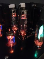
Here is my latest prototype, one channel of a proposed stereo SE hifi amp, seems to sound OK as is, now onto a proper build.
What tubes are you using?
What tubes are you using?
"Valves on my circuit are 12AU7 preamp and EL84 output"
His earlier response on my same question
Sorry, my answer too late.
Stevie, did you had the time to give the data of Vg2 and the voltage drop across that screen resistor?
Last edited:
If you have Heresies you should consider this:
Super Heresy 1 (Baby Cornwalls Mod.) - Technical/Modifications - The Klipsch Audio Community
Not too difficult to do but the results are simply amazing.
Super Heresy 1 (Baby Cornwalls Mod.) - Technical/Modifications - The Klipsch Audio Community
Not too difficult to do but the results are simply amazing.
At what voltage operates the Vg2 ? You have to determine the voltage drop across that screen resistor to get the correct resistor dissipation ( I thought this was your question?).
Have completely overlooked that the voltage drop across the resistor was already given
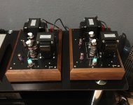
. So your calculation is correct. There is nothing to worry. enabled lockdown project - pair of EL504, good for 40+ pleasant watts!
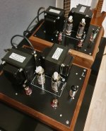
- Home
- Amplifiers
- Tubes / Valves
- Photo Gallery