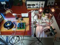
This amp too has been sitting like this for a long time, almost finished. It will be a variation of Kitic’s RH Universal amp, with Turner-like choke-loaded triode-connected power pentode as the driver. No time now, this summer probably...
Very smart looking. Nice work.
Very smart looking. Nice work.
Thank you! It sure is nice if every now and then form is on a par with function...
Last edited:
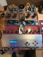
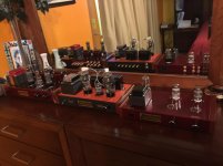
Hello, I pass some pictures of my amplifiers (version 1 and 2):")
What is this beauty??

Why? What difference does this make?
The load has been 8 ohms, i.e. 5k at the anodes. To switch 4 ohms load at 4 ohms output is the same 5k.
ok, just try heavier load, 20W/8R
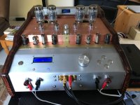
Well, great looking amplifier(s).Amplifier for headphone store. Two independent stereo amplifiers
But I am quite puzzled why you want to have two independent headphone stereo amplifiers on one chassis.
As already shown by my tests the 2.5 Vpp ripple at the plate voltage of the 845 output tubes generate 0.013 % (-78 dBc) 100 Hz IMD.
This is 6 dB below the IMD caused by the AC-heaters. I would like to know why would anybody need as low as 1-10 mVpp ripple (at PP-output stage) ?
You shouldn't due to CMRR, but obviously 2.5Vpp ripple is a lot for a single ended voltage stage with 6db PSRR like a common cathode amp
I made it for a headphone store. It would be possible to test two different headphones when working from the same source.Well, great looking amplifier(s).
But I am quite puzzled why you want to have two independent headphone stereo amplifiers on one chassis.
The store owner then said that customers quickly made their choice of headphones. He provided two models of headphones to choose from and set the buyer the desired musical composition. Or buyers brought their CD
Last edited:

Ah, Great idea from that store owner!. I noticed that you can choose between a low and a high impedance headphone.
Low = 30 Ohms ?
High = 300 Ohms (or higher)?
Any chance to share the circuit diagram? Or is it already published in the "Tubes/Valves" part?
This is a normal SE amplifier. The trasformer is recalculated to work with headphones. The outputs are designed for 25 and 100 ohms. Circuit and PCB for a single channel. 6N8S and 6P6S tubes. his amplifier Board has been available for 10 or 12 years.


Audio-O-Moron 40W amplifier
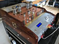
I have finally boxed my Raspberry Pi controlled P-P amplifier. It ended up rather monstrous! All metal sheet was hand beaten into submission. No a single laser cut to be found in this construction!
Summary:
P-P output stage using toroidal OPT
Bias monitored & controlled by the RPi
Takes a range of power tubes (6550, KT88, 6L6, EL34 etc), the Rpi makes the bias adjustments as set from front panel (25-90mA)
B+ approx 400V
Driver is Pete Millet's P-P driver boards
Tone control is Braxandall. Can be switched off & out of the circuit via the front panel.
Pout = 40W RMS into 8 Ohm (visible distortion on scope)
Distortion at 2W is approx 0.1% (2nd & 3rd harmonic)
Attachments
That's the dedication. I had one of those 10 years ago. They weight approximately metric ton. Had to sell as it was incompatible with any living space.For output tubes I used in the beginning a pair of Soviet made UIP-1 (600 V / 600 mA).
Universal-Netzanschlussgerat- Deutsch Power-S Unknown - CUSTO
I have finally boxed my Raspberry Pi controlled P-P amplifier. It ended up rather monstrous!
It has its own charm for an engineer without WAF-issues
Anyway congrats for finishing such a build. Hopefuly the RPi is online and can be controlled by an app
I have finally boxed my Raspberry Pi controlled P-P amplifier. It ended up rather monstrous! All metal sheet was hand beaten into submission. No a single laser cut to be found in this construction!
The only way it should be done. I once saw a video of some Indian(?) guy making a VW floor pan out of a piece of sheet metal using nothing but a hammer and a couple blocks of wood. The result was pretty impressive. So is this amp.
Member
Joined 2009
Paid Member
I have finally boxed my Raspberry Pi controlled P-P amplifier. It ended up rather monstrous! All metal sheet was hand beaten into submission. No a single laser cut to be found in this construction!
Pout = 40W RMS into 8 Ohm (visible distortion on scope)
Distortion at 2W is approx 0.1% (2nd & 3rd harmonic)
wow! that looks like a lot of work and great result. Any photos of the inside?
Any photos of the inside?
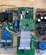
Here are 2 inside photos, the first is the lower chassis with the auxiliary PSUs and RPi:
5V for RPi with LiPo 3.7V charger & backup 15V for the LT3751 capacitor charger demo board (that I had salvaged from a previous project) which generates the -110V for the control grid supply +-15V for the grid voltage amplifiers 18V ac for the driver board, to generate the -Vneg needed Filament rectifier & relay control
The 2nd photo shows the driver & power tube arrangement with the bias control. The 3 toroids are B+ PSUs and the centre for filament. The OPT are below the power tubes.
Attachments
- Home
- Amplifiers
- Tubes / Valves
- Photo Gallery