Member
Joined 2009
Paid Member
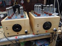
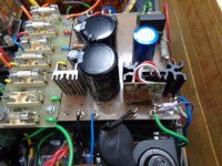
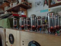
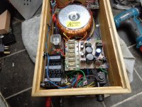
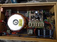
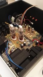
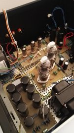
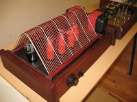
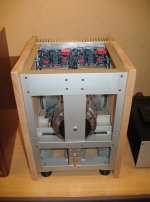
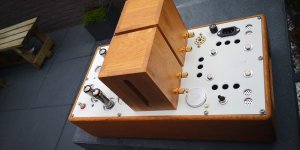
that’s a lot of work!Here are 2 inside photos.
Wavebourn,
Real Nice!
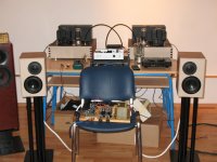
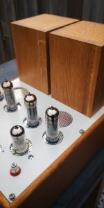
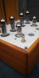
Are those tubes on the middle amp 807s?
No, 4П10С
Like VT-127/CV1127, pretty linear classified sweep tubes for radars.
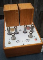
I've finally finished my first valve amp build, it's taken about two years. I built the amp once in one chassis, wasn't happy so started again.
Each mono block has it's own PSU with a 625VA handwound/overwound toroid mains tfmr with 9 second soft start for the HT/B+. There is also two protection circuits so that that if Ik of each EL34 exceeds 100mA a thyristor engages a relay that cuts the neutral to the main tfmr as well as no speaker/load protection.
Specs - 0.01% @ 1w, 0.07% @ 10w, 0.21% @ 50w and 0.28% THD @ 112.5w this at 1khz. N/ripple = 20mV. F response 3dB @ 1dB @ 5hz, flat to 28khz, 3dB @ 33khz.
Valve line up 6AU6 triode strapped for the front end with CCS load, two ECC99/6H6N's as the LTP phase splitter with CCS in the tail.
OPT's are Hammond 1650TA, caps 105 deg mostly of reputable makes, Bourn pots, Vishay resistors so most components of good quality but not boutique.
Woodwork is sycamore, hand planed from a tree, took ages as my tools are very basic. Chassis handmade from 2mm ali sheet.
Lastly though the design of most of the amps is my own work I lifted quite a few ideas of Patrick Turner and also picked his brains via email, thanks Patrick. Anyone wishing to build high powered amps or any valve/tube amp should have a butchers at his site, an invaluable resource for tinkerers and artificers.
Andy.
Attachments
-
 EL34 120w monoblocks.JPG161.3 KB · Views: 994
 -
 6.3v regulator, bias and soft start board and AC fuse board.JPG160.8 KB · Views: 244
 -
 DSC01339.JPG161.5 KB · Views: 248
 -
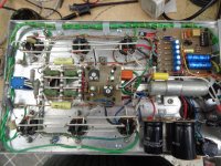
 12 EL34's.JPG160.5 KB · Views: 282
 -
 PSU.JPG162.1 KB · Views: 925
 -
 PSU - capacitor board, SS relay,chassis connect, etc.JPG160.3 KB · Views: 958
 -
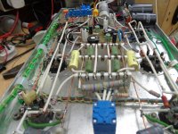 Amp chassis, balance pot in foreground.JPG161.7 KB · Views: 966
 -
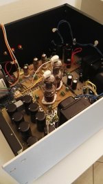
 Underside of amp chassis.JPG162 KB · Views: 987
 Discussion for the above amplifier has been moved to: 120w PP UL monoblocks
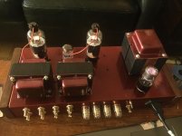
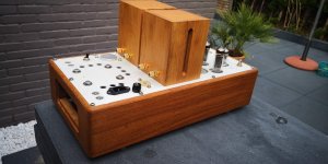
Additional switch to decrease active dumping and a mono subwoofer output on the rear panel.
Wow! You produce so many beautiful amplifers!
What is "active dumping"?
Wow! You produce so many beautiful amplifers!
I am building prototypes and sell them to people, while listening to their desires figure out what options to offer when production will be available. It is a R/D phase with trials and errors, "What people want".
What is "active dumping"?
Negative output resistance. Traditional "Damping Factor" is a marketing-driven number. When output resistance of an amplifier is already significantly below DCR of speakers, further increase of that "Dumbing Factor" has no meaning. Negative output resistance partially compensates DCR providing real damping, even extending frequency response a bit below the main speaker's resonant frequency, when it's impedance goes down to DCR.
Wavebourn - What servo control of speakers mean | Facebook
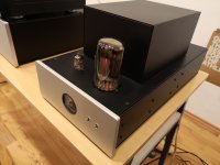
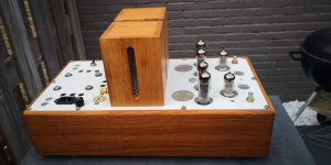
Hi all, here the first, almost completed, of the two monoblocks: 40W with 6N23P input, 6E5P driver, G-807 output. Separated CLC supply for input - driver and output tubes. Fixed bias.
Attachments
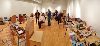
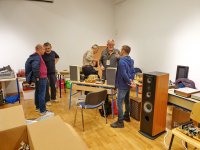
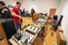
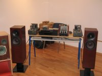
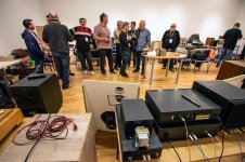
...just a hint of 10th Croatian Triode Festival, last weekend  ... we are now on double digits ... as usual - good people, good friends, good music... and some electronics and food, not to forget craft beer(s) and other delights... a short video is here:
YouTube
... we are now on double digits ... as usual - good people, good friends, good music... and some electronics and food, not to forget craft beer(s) and other delights... a short video is here:YouTube
Attachments
-
 20190517_205806.jpg735.3 KB · Views: 1,020
 -
 20190518_114029.jpg460.1 KB · Views: 975
 -
 60630986_2082596922048410_2491289487917711360_n.jpg131.3 KB · Views: 1,010
 -
 60735706_2514763761869515_3642985475146252288_o.jpg283.5 KB · Views: 956
 -
 60803936_2514766555202569_474261502983929856_o.jpg631.2 KB · Views: 526
 -
 60651285_2514765515202673_7776072696391008256_o.jpg435.4 KB · Views: 465
 -
 60661264_2082596808715088_4178435749403688960_n.jpg150.7 KB · Views: 464
 -
 60628372_10157054685549693_6008867437053739008_o.jpg398.1 KB · Views: 498
 -
 60500093_2514765368536021_3451510928237920256_n.jpg139.9 KB · Views: 529
 -
 60981900_10157054685784693_2658447527723925504_n.jpg126.1 KB · Views: 1,019

Integrated Edelweiss-3
............... and a mono subwoofer output on the rear panel.
I have often wondered how to build a "sub out" feature into a tube amp.
Would you be willing to share this circuit?
You see this often in vintage amps for a center channel output. A 10K resistor connected to each + speaker output, then connected together then with a 2K resistor from that junction to ground will provide a reasonably well isolated subwoofer output, assuming of course that the other end of your OT winding is grounded.
Yes, exactly like this. If a crossover is needed, one cap can be added for 6 dB/Oct, or even one more RC for 12 dB/Oct.
Here is the first audio test:
Wavebourn - Edelweiss-3 for Australia | Facebook
Here is the first audio test:
Wavebourn - Edelweiss-3 for Australia | Facebook
Tubecad pushpull el84.
Changes: 20k plate load resistors for the 6n1p.
Changes: 20k plate load resistors for the 6n1p.
Attachments
Last edited:
Tubecad pushpull el84.
Changes: 20k plate load resistors for the 6n1p.
A Decware with more power! You skills and taste are awesome! Compliments
- Home
- Amplifiers
- Tubes / Valves
- Photo Gallery