FastEddy said:HDaudio: ...
" ... shouldn't there be some... uh... "tubes" in there? ..."
Not to worry. We will just have the moderator pass these pics and build descriptions over to the Digital section ...
I like it, and I'm glad you shared this with us. How does it sound?
Thank for asking me !
I m like Tube , but, my music love oly Classic and some time with POP thats problem for Tube when use system have CDplayer with Tube out, and Preampli tube togethe, soud not good to much for Classic , Thats my idiea when hearing its sometime have fun !

I m thinking not now , but future Im do analogue out put in CDP with SE mofets.
Everybody here have Schema for thats ? Please help me !
Thank for all !
My finaly finished amplifier:
Beautiful! That's my style of amp, timeless...
Simon
PX25 class A transformer coupled, cathode feedback design (separate power supply).
At the workbench
Out in the sun
Measurements:
Power output: 2x15W
THD: 0.16% (-56dB) (1dB below rated Po)
Power bandwidth: 16Hz-40kHz +0/-3dB
Output impedance: 1.1 ohm
CFB: 6dB
Work log (Norwegian): -> http://www.veiset.net/PX25/worklog.html
Jan E Veiset
At the workbench
An externally hosted image should be here but it was not working when we last tested it.
Out in the sun
An externally hosted image should be here but it was not working when we last tested it.
Measurements:
Power output: 2x15W
THD: 0.16% (-56dB) (1dB below rated Po)
Power bandwidth: 16Hz-40kHz +0/-3dB
Output impedance: 1.1 ohm
CFB: 6dB
Work log (Norwegian): -> http://www.veiset.net/PX25/worklog.html
Jan E Veiset
FastEddy said:ooohhhh aaawasome!!
How did you do that woodwork?? vertical mill? layers?
For that part I've got help from someone with access to CNC machinery.
Jan E Veiset
Re: E55L Line Amp
Looks like military equipment! Nice!
845 said:And inside........
Looks like military equipment! Nice!
After browsing this thread (which takes a while) I'm glad to be able to post something different.
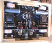
It is a design for a single ended power amplifier for use with a Benchmark DAC1 D/A converter.
The amp consists of a Lundahl 7905 input transformer directly connected to the grid of an EML 300B-XLS (autobias, 90mA 420V), a Lundahl 1623 ouptut transformer is used to connect the loudspeaker (Fostex208? in Schmacks BLhorn).
Single Tube Impedance Transformer
The power supply is all solid state (yes, it does sound excellent), heavily filtered and fully regulated. Total hum & noise on the output: -84dBV (63µV)
0dBFS on the DAC1 yields 6.2W output power. More specs can be found here
Gerrit Boers: Very sweet, very Buck Rogers ...
... Is that a copper PS chassis?
... Also since you have access to tools and your design is "open frame" (sans shielding), are there any indications of outside interference imposing on the output quality?
Would love to see the schematic ...
... ... Is that a copper PS chassis?
... Also since you have access to tools and your design is "open frame" (sans shielding), are there any indications of outside interference imposing on the output quality?
Would love to see the schematic ...
BeeGee2
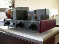
I just finished this amplifier today and have listened for several hours. Overall it sounds good to my non-audiophile ears. This is my first strictly audio project and my first time building with tubes, though I have repaired a few tube radios. I chose this project because I thought it would be a lot easier to build a tube audio amp than a tube radio (based on my experiences building solid-state radios). I am fairly certain now that I was wrong about that: not easier, different.
The input (12AX7) and buffer/phase splitter (6AU6) circuit ideas came from an old TAB book 104 Simple One-Tube Projects. The outputs (6EZ5) started as a basic push-pull circuit I found in an old ARRL book, then got modified into an ultralinear design as I read and learned more. The heaters are all AC. The HV supply uses a 5U4GB rectifier and a CLC filter. There is a bit of 60HZ hum, but I cannot hear it 2 feet away from the speakers. The chassis is 1/16" steel that came from a scapped computer power supply. The green is high-temperature engine paint leftover from repairs on my motorcycle.
Early listening:
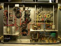
Underneath:
More pictures here.
I will probably get rid of the meters: they were good on the prototype build, but really don't fit this chassis and they only respond to very low frequencies. When I am happy with the sound, it will go on a wood base with oak side rails (not fabricated yet).
I do have questions about tuning the circuits for sound quality and frequency response, but I would like to listen for a few days to get a better idea of what I like and don't like about the way it sounds. I will start a new thread for that and post the schematics there.
Thanks for making this forum available, you all have answered many of my questions without me even having to ask !
Ben N1NP
I just finished this amplifier today and have listened for several hours. Overall it sounds good to my non-audiophile ears. This is my first strictly audio project and my first time building with tubes, though I have repaired a few tube radios. I chose this project because I thought it would be a lot easier to build a tube audio amp than a tube radio (based on my experiences building solid-state radios). I am fairly certain now that I was wrong about that: not easier, different.
The input (12AX7) and buffer/phase splitter (6AU6) circuit ideas came from an old TAB book 104 Simple One-Tube Projects. The outputs (6EZ5) started as a basic push-pull circuit I found in an old ARRL book, then got modified into an ultralinear design as I read and learned more. The heaters are all AC. The HV supply uses a 5U4GB rectifier and a CLC filter. There is a bit of 60HZ hum, but I cannot hear it 2 feet away from the speakers. The chassis is 1/16" steel that came from a scapped computer power supply. The green is high-temperature engine paint leftover from repairs on my motorcycle.
Early listening:
An externally hosted image should be here but it was not working when we last tested it.
Underneath:
An externally hosted image should be here but it was not working when we last tested it.
More pictures here.
I will probably get rid of the meters: they were good on the prototype build, but really don't fit this chassis and they only respond to very low frequencies. When I am happy with the sound, it will go on a wood base with oak side rails (not fabricated yet).
I do have questions about tuning the circuits for sound quality and frequency response, but I would like to listen for a few days to get a better idea of what I like and don't like about the way it sounds. I will start a new thread for that and post the schematics there.
Thanks for making this forum available, you all have answered many of my questions without me even having to ask
!Ben N1NP
Gerrit Boers: Very sweet, very Buck Rogers ...
... Is that a copper PS chassis?
... Also since you have access to tools and your design is "open frame" (sans shielding), are there any indications of outside interference imposing on the output quality?
Would love to see the schematic ...
Yes the PS chassis is coppper, soldered together with angled brass profiles. The side panels are not polished yet, that's why the chassis is open. There might be some interference in the HF range, my Clio systems can measure up to 22KHz, but the audio range is very clean.
The schematic for the amp can be found here:
SiTuIT 2
The schematic for the PSU is al over the place:
High voltage schematics (look at the bottom of the page)
Heater supply
Re: BeeGee2
A Kawasaki?
dave
n1np said:The green is high-temperature engine paint leftover from repairs on my motorcycle.
A Kawasaki?
dave
- Home
- Amplifiers
- Tubes / Valves
- Photo Gallery