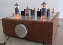
mcgaag said:My first diy tube amp sounds so good, i decided to built a proper housing for it because it probably will be in my living room for a long time. (at least until the next one is ready)
Very Nice!
mcgaag said:My first diy tube amp sounds so good, i decided to built a proper housing for it because it probably will be in my living room for a long time. (at least until the next one is ready
Very nice indeed !
My monoblock 2x125W 833 tube set amplifier slide show
:Slide show:
http://img507.imageshack.us/slideshow/player.php?id=img507/1028/1246301822toi.smil
An externally hosted image should be here but it was not working when we last tested it.
An externally hosted image should be here but it was not working when we last tested it.
:Slide show:
http://img507.imageshack.us/slideshow/player.php?id=img507/1028/1246301822toi.smil
Re: My monoblock 2x125W 833 tube set amplifier slide show
That's pretty nice but what have you done to keep every single person that will ever be near your amplifier even if you are not immediately present to watch them and warn them of the certain death hazzard of coming in contact with the exposed anode cap on the big output tube that is right out in front within easiest reach? Have you made legal arrangements through your estate plan that will guarantee that this amplifier is destroyed upon your possible incapacitaion due to accident or illness or when you eventually die in order to protect other human beings?
noyan said:
That's pretty nice but what have you done to keep every single person that will ever be near your amplifier even if you are not immediately present to watch them and warn them of the certain death hazzard of coming in contact with the exposed anode cap on the big output tube that is right out in front within easiest reach? Have you made legal arrangements through your estate plan that will guarantee that this amplifier is destroyed upon your possible incapacitaion due to accident or illness or when you eventually die in order to protect other human beings?
http://www.flickr.com/photos/12596932@N02/3675835836/in/set-72157601854797815/
http://www.flickr.com/photos/12596932@N02/3675842156/in/set-72157601854797815/
http://www.flickr.com/photos/12596932@N02/3675845668/in/set-72157601854797815/
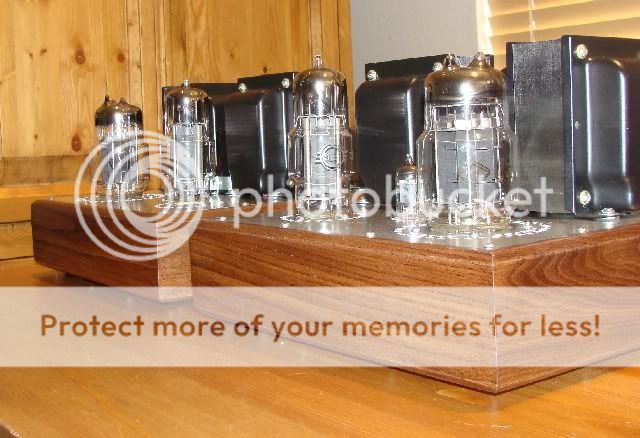
It's my & my friend's work....6C33C & 6E5П - PS is on the right side. Wights - 29 and 35 kg
http://www.flickr.com/photos/12596932@N02/3675842156/in/set-72157601854797815/
http://www.flickr.com/photos/12596932@N02/3675845668/in/set-72157601854797815/
It's my & my friend's work....6C33C & 6E5П - PS is on the right side. Wights - 29 and 35 kg
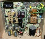
This is a picture of the inside of the amplifier during test and in a pine chassis. The lead dress is much better in the finished amplifier, but you can get a good idea of the "guts" from this picture.
On the right side are the low voltage transformers for the bias and JFET input stage, and the large Solen capacitor is the CLC output capacitor. The high voltage regualtor board is in the center of the picture and provides a regulated B+ for the tube amplifier and drive stages. The bottom left are the 5 Volt 300B filament transformers and above them is the input stage and constant current sources. Top left is the rectifier tube and the first filter capacitor.
This amplifer uses cathode feedback on the output stage and has a tube compliment of a 6SL7, 6SN7, 6BL7, GZ37 (or 5V4G) and a pair of 300B's.
Attachments
Hello Felixx,
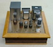
I used custom Edcor transformers for both power and output. The input/driver tube is a 6F1P (equivalent to ECF180). The pentode section of the 6F1P is used as the input/gain stage. The triode section of the 6F1P is the second stage, which is a cathode follower that is direct coupled to the first stage. The cathode follower stage drives the 6c33c.
The other large tube you see is a 5c8s rectifier tube. It is a good match for the 6c33c both in appearance and characteristics. It's a low impedance high current rectifier tube.
- Home
- Amplifiers
- Tubes / Valves
- Photo Gallery