sorry, stupid typo in the worksheet: R11-14 and R15-18 were mislabeled.
modded my prototype to bring it in line with what I have been suggesting:
R9,10 : 100 ohms (changed from 300)
R11-14 : 10k (changed from 15k)
R15-18 : 1k
R19-20 : 33k
Output voltage is now 11.1 V. That's within 0.5 V of what my worksheet predicted. Sounds the same as before.
modded my prototype to bring it in line with what I have been suggesting:
R9,10 : 100 ohms (changed from 300)
R11-14 : 10k (changed from 15k)
R15-18 : 1k
R19-20 : 33k
Output voltage is now 11.1 V. That's within 0.5 V of what my worksheet predicted. Sounds the same as before.
Attachments
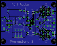
I feel happy enough with the phonoclone 3 circuit to include it in the list of options on the web page: RJM Audio PCB page
I've been catching up with the backlog of unread posts at the help desk. I know a number of people have had hum/RFI problems, and several people have offered useful suggestions. I'll try to leverage that into the pcb design as much as possible.
The latest revision of the board includes the option of a small capacitor C0 across the opamp inputs. If your phonoclone is acting as a radio, try adding a capacitor here. A few hundred pF should suffice, but some trial and error may be required.
Other things:
1. Never, ever use unshielded phono cables.
2. Ground the turntable/arm to the phonoclone case.
3. Set R2 to no more than 30x the cartridge impedance. Ignore my earlier comment that R2 should not be less than 500 ohms. For the small signals involved it shouldn't matter.
Attachments
Nice work
It all looks very nice.
Experience with my previous phoneclone's build components did not change the sonic charater as much as the different power supply arrangements did.
This PS layout would be a new route for me, having thought about the superregulators before. Do you have already any hints on the sonic character vis-a-vis the previous versions?
Regards,
Michiel
For those with hum on previous phonoclones, this:
may be important. When I reduced my gain (by setting R2 to about 300-400R) the hum went. I found it by accident when using a MC cart but with a highish ouput (0.24mV, zyx bloom) I had to reduce R2 to get a lower gain. No hum. When I hooked my other rig up, there was no hum.
Fran
3. Set R2 to no more than 30x the cartridge impedance. Ignore my earlier comment that R2 should not be less than 500 ohms. For the small signals involved it shouldn't matter.
may be important. When I reduced my gain (by setting R2 to about 300-400R) the hum went. I found it by accident when using a MC cart but with a highish ouput (0.24mV, zyx bloom) I had to reduce R2 to get a lower gain. No hum. When I hooked my other rig up, there was no hum.
Fran
@Michiel: Ok, I'll take a stab at it:
What you mainly get is clarity, top to bottom. Reaching for an analogy, it's like submitting the recording to a high-pressure steam cleaning. You can hear, and feel, everything. To be honest, it's disorienting. I'm still at the "is this really real?" stage of disbelief.
The one thing still worrying me is whether it somehow manages to artificially enhance certain elements, particularly percussive sounds, which would give a false impression of improved dynamics and resolution. The more I listen, the less I am inclined to believe this to be the case. However, in fairness I feel I should point it out.
Anyway, there is a physicality, a palpable sense of things coming out into the room that, well, isn't always so pleasant. If I would sum up my impression so far in a single word it would be:
"yikes".
That isn't stopping me from cuing up record after record though. Through the Twilight headphone amp especially, it's quite a treat.
If what I'm hearing is "real", very minor tweaks to the circuit should not have a great effect. If on the other hand it is the result of some oscillation or other instability it should be easily suppressed or at least drastically altered by the same tweaks.
So, time to do some tweaking!
First thing was to remove C12 and C13, which were always considered optional. This puts a bit of trace length between the pass transistors and the first electrolytics, situated next to the Phonoclone's op amps.
This had a pretty significant effect of "winding down" some of the punchiness. I should say the sound seemed slightly more natural, but less dynamic than before.
The next thing to try was adding a small resistor between the op amp output and the transistor base. I'd played with this earlier on the test bench, but the OP27 was stable without so I left it out of the boards I had made. If you notice at Tangentsoft's excellent review the original Sulzer circuit may not have had them, every later iteration did. A small detail worth noting.
http://tangentsoft.net/elec/opamp-linreg.html
It was a hack - literally - but I went and retrofitted 47 ohm resistors. Quick and dirty method: cut the signal trace and solder the resistor across the pins of the op amp and transistor on the underside of the PCB.
This time, the difference was night and day. In short, the sound became normal: softer, fuller, but less distinct. Although more in line with what I'm used to hearing, it's still a fair bit better than my RC.
Oh well, it was fun while it lasted but I think I prefer it this way.
My guess is that the OP27 is not especially happy having the capacitance of the pass transistor inside its feedback loop. I don't know the exact mechanism for the loss of stability, if indeed that is what it was.
Working eagle files updated to reflect current situation. Sorry, the capacitance numbering was changed in the latest version.
Attachments
Hopefully this is the last update of the Eagle files I'll need to post for some while, at least until the other beta testers get back to me with suggestions.
Changes in 31i:
- Tidied up the component layout around IC3 and IC4.
Changes in 31h, above:
- Changed R9, 10 back to 220 ohms. It's no big deal, but it just seemed prudent to drop the voltage down to around 15 V.
- Moved some filter capacitors around, removing the two at the transistor output and adding them to the V+ and V- rails so that each op amp IC3,4 will have bypass caps a little nearer to the power pins.
- Added R21,22 47 ohm resistors between the output of IC3,4 and the base of transistors Q1,2.
Attachments
OK,
I've updated my BOM, most likely will order in the early days of next week, all going well.
If anyone wants an excel file with all mouser part numbers and quantities to stuff 2 boards, shoot me an email and I'll send it to you.
****************************
RJM, what do you think of the sound now? Is it still well ahead of the phonoclone regular? The thing you are talking about, that punchiness, it might not be any harm for it to be gone. I'm just thinking that something like that might be great for a while, but long term might be fatiguing. One of the great strengths of the regular phonoclone is that it never puts a foot wrong in that department. The detail etc is always there, but it always sounds natural.
I'm looking forward to trying it out....
Fran
I'm relying on you Fran to make that comparison for me.
I do think this new circuit is big improvement. To be honest though, it bothers me that a voltage regulator that on paper seems pretty much a done deal is ending up to be so susceptible to tweaking. Perhaps it's just that the lower noise floor means you can make out rough edges that would otherwise have gone unnoticed, but I think its more the case that these DIY voltage regulators are actually a fair bit harder to get really, truly stable than you'd ever guess from reading the datasheets or write ups.
My feeling is that even though we've made great strides there are still probably a couple of gremlins in there that need to be flushed out.
Note that I'm being way, way tougher on this latest revision than any previous build. That's because I now have a very good headphone+amp, so I'm doing most of the listening via HD600s rather than my gainclone+rather lacklustre speakers.
/rjm
oh yeah, well headphones are very revealing at this sort of thing. They are ruthless at showing up any kind of noise, plus harshness and so on. You will pick up stuff that would pass unnoticed through the speakers.
The only thing that they can't tell you about, and its a pretty big thing when it comes to vinyl, is soundstage. Vinyl is so good in this area, that if the soundstage is dull and lacklustre, it will make or break the phonostage. And I have to tell you that the regular phonoclone is very good at soundstage and naturalness. Things like simple but good recordings, verve/impulse etc sound great with it. Good depth. On busier music, it manages to separate out enough to give good resolution, gives a sense of space and air, no congestion. I have compared it with a few others, like the loecsh tube pre and a tom evans one, and the phonoclone can hold its head high.
So if the rev 3 can take that trick and bring it to another level... it will be a fine phonostage indeed.
**************************************************
I am a little worried about using the wimas for C3 and then comparing those to the blackgates I have in my other phonoclones. I had tried other caps in there, and heard pretty major improvement when I added the blackgates. So I'm really hoping the wimas don't cloud my judgement. In any case I think I will install some sockets for C3 (and R2) and allow myself to be able to swap them out. I think I will do the same for the optional caps (c12 and 13 IIRC). Traces are easy enough to tear so sockets make life easy.
Keep us informed RJM!
Fran
Just another thing RJM: it may sound like the easy (sleazy?) way out, but just in case something is proven to be dodgy with the regulator, it might be a good idea to somehow include the possibility to bypass the onboard regulator to allow someone to use an outboard super reg, eg the teddyreg/alwsr/jung variant or even something like the toolereg ones in the current group buy. If an extra set of V_input holes were added, and a jumper to cut off the onboard regs.... I know it sounds harsh to even suggest it!!
It would also be interesting as an experiment to compare the opamp regulator vs. something as cheap as a teddyreg... would allow you to find out if the dramatic changes are "true" or really down to instability. Also it would allow you to compare the different PS approach.
Lastly - could you adjust the pin spacing for the V_inputs so that you could use a PCB header, say a screw terminal for the V inputs? Those things are really handy when it comes to board swapping time.
Is this crazy stuff to be suggesting? I don't know enough to help with any of this, all I can really do is build! I'm a blocklayer, not an architect when it comes to this stuff.
Fran
Let me take those up individually:
It's not very difficult to bypass the onboard regs, though it's not quite as simple as a jumper: just desolder the pass transistors and feed the external voltage directly to pad 3.
Agreed, the solder pad connections have frustrated me on a number of occasions. I'll have a look at it. What pin spacing would you prefer, 0.1, 0.15 or 0.2 inch?
I did a marathon testing session last night, repeated AB changes. Leaving me more confused than ever unfortunately.
The best explanation is by analogy, just don't take it too far;
The Phonoclone RC I have is like watching a DVD with a very good DVD player.
The Phonoclone 3 is like watching Blu Ray on an mediocre Blu Ray player.
While you can make a case for the DVD player having slightly better contrast, or slightly more accurate colors, for example, at the end of the day Blu-Ray is giving you at least 4 times as much information, and a vastly clearer picture. Of course to take advantage of that you need a good monitor, and taking the analogy one step further, flaws in the original source or indeed anywhere in the playback chain become that much more obvious, to the point where it can be annoying even.
I should stress that both phonoclones sound very much alike. From a purely sonic standpoint the RC actually is slightly more pleasant to listen to in that the tone is warmer and more laid back. But, in direct comparison the RC conveys only most rudimentary information about what's going on the recording. The RC has sounds from the left, right, middle. The '3 as every instrument isolated and reconstructed in minute detail. Yes they sound very much alike, yet it's hard to believe at times its the same LP!
woodturner-fran said:...it might be a good idea to somehow include the possibility to bypass the onboard regulator to allow someone to use an outboard super reg...
It's not very difficult to bypass the onboard regs, though it's not quite as simple as a jumper: just desolder the pass transistors and feed the external voltage directly to pad 3.
- could you adjust the pin spacing for the V_inputs so that you could use a PCB header, say a screw terminal for the V inputs?
Agreed, the solder pad connections have frustrated me on a number of occasions. I'll have a look at it. What pin spacing would you prefer, 0.1, 0.15 or 0.2 inch?
I did a marathon testing session last night, repeated AB changes. Leaving me more confused than ever unfortunately.
The best explanation is by analogy, just don't take it too far;
The Phonoclone RC I have is like watching a DVD with a very good DVD player.
The Phonoclone 3 is like watching Blu Ray on an mediocre Blu Ray player.
While you can make a case for the DVD player having slightly better contrast, or slightly more accurate colors, for example, at the end of the day Blu-Ray is giving you at least 4 times as much information, and a vastly clearer picture. Of course to take advantage of that you need a good monitor, and taking the analogy one step further, flaws in the original source or indeed anywhere in the playback chain become that much more obvious, to the point where it can be annoying even.
I should stress that both phonoclones sound very much alike. From a purely sonic standpoint the RC actually is slightly more pleasant to listen to in that the tone is warmer and more laid back. But, in direct comparison the RC conveys only most rudimentary information about what's going on the recording. The RC has sounds from the left, right, middle. The '3 as every instrument isolated and reconstructed in minute detail. Yes they sound very much alike, yet it's hard to believe at times its the same LP!
Pin spacing: I dunno, I suppose 0.2" (5mm) cos thats what I have in stock and theya re easy to get?
Thats good to know about adding the external PS. When all the dust settles, it might be a good thing to try. I might just install the transistors on sockets too!
*******************************
Your description is intriguing. In fact the kind of thing you're talking about almost sounds like what you'd hear from a new piece of kit that needed a while to burn in. I wonder if thats going on here. I wonder if its also to do with those C12 and c13 caps - what about if we put in something else there, like blackgates or even some film caps. Might add back some of the dynamics and help soften out.
I suppose I'm trying to say that I get the sense that the last bit of what it is that you're missing is tweakable. Something like a change of cap or maybe bypassing a cap might do it.
Interesting!
Fran
31j just for you Fran ")
****
Yes, definitely tweakable ... and, uh, not necessarily the phonoclone. I've just finished giving my stylus a scrubbing and readjusted the elastomer in my DA-307 tonearm. I'm now grooving to Al Stewart ... oh, at 100% improvement vs. earlier today. A number of things I'd pegged on the phonoclone (lack of body, fullness, skidding out of control on transients) turned out to be in the arm/cart instead!
The take home message though is the Phonoclone 3 is that much better: every change - and error - upstream is clearly visible, where it just wasn't before.
I share your confidence that whatever is left to wring out of the Phonoclone is mostly a matter of layout, value and distribution of the capacitors, with, as a last resort, a cap across the feedback resistors of IC3,4 to kill off the bandwidth.
Attachments
Ah yes, now that is good to hear. Reminds of one time when I thought I had some sibilance on vinyl that wasn;t there at all on CD. So after much changing of cables and so on, I doscovered that my cartridge alignment was off a bit. Only revealed when i ran a quick test with the HFNRR test record and the tracking ability was worse than when I set it. There was a loose bolt holding the arm post.....
Now I'm doubly looking forward to it.... and did you leave out C12 and 13 as earlier?
Fran
Now I'm doubly looking forward to it.... and did you leave out C12 and 13 as earlier?
Fran
- Status
- This old topic is closed. If you want to reopen this topic, contact a moderator using the "Report Post" button.
- Home
- Source & Line
- Analogue Source
- Phonoclone 3