I must have been loosing concentration by the time I'd got to that part of the design.
Your net list or design rule check should have caught that.
Sorry to resurrect this one... I've put together two boards now and I have a couple of niggling problems.
The main one is that I have what I assume is RF interference (burbling & clicking with a distinct pattern to it). If I power up the TT amp with no input (the RCA sockets short themselves when nothing's plugged in) I can turn the volume on the power amp right up and it's silent. However if I plug in the TT I get the interference even when it's not playing. The board is in a grounded aluminium chassis and I have the TT ground connected to the same star point.
This doesn't happen on my other TT amps so I think it must be something to do with my design... any ideas?
The other problem I've been having is varying success with the servos, I've had to play about quite a bit to get the servos working and I can't work out why they are so temperamental. I've had everything from +60mV offset to a steady 0.5mV. I've continuity tested the board and re-flowed the solder on the ICs a couple of times - I've now got <1mV on both channels but the offset fluctuates rapidly... should that be happening?
Any help would be greatly appreciated.
Thanks.
You mention to have had problems with your servo, what exactly were these problems ?Sorry to resurrect this one... I've put together two boards now and I have a couple of niggling problems.
The main one is that I have what I assume is RF interference (burbling & clicking with a distinct pattern to it). If I power up the TT amp with no input (the RCA sockets short themselves when nothing's plugged in) I can turn the volume on the power amp right up and it's silent. However if I plug in the TT I get the interference even when it's not playing. The board is in a grounded aluminium chassis and I have the TT ground connected to the same star point.
This doesn't happen on my other TT amps so I think it must be something to do with my design... any ideas?
The other problem I've been having is varying success with the servos, I've had to play about quite a bit to get the servos working and I can't work out why they are so temperamental. I've had everything from +60mV offset to a steady 0.5mV. I've continuity tested the board and re-flowed the solder on the ICs a couple of times - I've now got <1mV on both channels but the offset fluctuates rapidly... should that be happening?
Any help would be greatly appreciated.
Thanks.
To start with, remove the 1 K resisistor from the output of the servo to disable this servo function and switch of the rumble filter.
Now only the input and the output amps are in the chain.
The output amp has a gain of 1 in its lowest gain setting, so has the input amp for DC.
With a typical Vos of 0.5 mV, the output DC voltage should be around 1mV, assuming you are still using the OPA1652, right ?
Setting the output amp in its highest gain of ca 11x, output offset should be 11 mV max.
So when you mention 60 mV at the output, this indicates that something is wrong.
Whenever the output voltage without servo is like calculated above, connect the Servo.
DC output voltage should now be below 1mV at all times, independent of gain settings.
When the Servo seems a bit too "temperamental", you could temporarily increase the value of the two 100nF caps with 1uF caps just making the servo 10 times slower.
Let's see what your response is to these steps.
Hans
Thanks for the suggestions Hans I'll do as you say.
The two problems I have are (1) RF interference and (2) getting the Servos to work consistently... I'll work on the servo problem first and post the results.
I'm still using the OPA1652 and everything is pretty much as in the last schematic (bar the correction you pointed out).
The two problems I have are (1) RF interference and (2) getting the Servos to work consistently... I'll work on the servo problem first and post the results.
I'm still using the OPA1652 and everything is pretty much as in the last schematic (bar the correction you pointed out).
Thanks for the suggestions Hans I'll do as you say.
The two problems I have are (1) RF interference and (2) getting the Servos to work consistently... I'll work on the servo problem first and post the results.
I'm still using the OPA1652 and everything is pretty much as in the last schematic (bar the correction you pointed out).
You need an RF filter on front end.
If the servo output is moving fast then you could try increasing capacitor in servo circuit.
Re-reading Douglas Self I now remember that RF filtering is supposed to be provided by the cartridge loading capacitors - keeping them as close to the input as possible is supposed to provide some filtering of RF. I got them pretty close in the final layout - but they are switched so the traces are longer than if they were direct. It hasn't been a problem with my other TT Amps (but I'm now thinking I'll plug them back in to check).
Cartridge loading with the correct cap is not meant to do any RF filtering but to adjust the FR in the upper octaves.Re-reading Douglas Self I now remember that RF filtering is supposed to be provided by the cartridge loading capacitors - keeping them as close to the input as possible is supposed to provide some filtering of RF. I got them pretty close in the final layout - but they are switched so the traces are longer than if they were direct. It hasn't been a problem with my other TT Amps (but I'm now thinking I'll plug them back in to check).
There is no reason whatsoever to do any RF filtering in the signal line.
Important is that the power supply of the OpAmps is decoupled correctly with 100nF caps as close to the amps as possible.
What sort of power supply are you using to feed this circuit ?
Strange symptoms with fast Opa's usually point in the direction of HF oscillations.
What happens with the output DC voltages when you connect your TT, still without servo and rumble filter.
If you do not find anything that's wrong, you will definitely need an oscilloscope.
Hans
The power supply is as post #35 on this thread.
I've decoupled the op-amps with 100nF, the right channel (which is the one with the problem) has a shorter route for the caps than the left.
I'll try out connecting the TT and checking the voltages - I have a scope I can use to make further measurements.
I've decoupled the op-amps with 100nF, the right channel (which is the one with the problem) has a shorter route for the caps than the left.
I'll try out connecting the TT and checking the voltages - I have a scope I can use to make further measurements.
Power supply seems more than adequate.The power supply is as post #35 on this thread.
I've decoupled the op-amps with 100nF, the right channel (which is the one with the problem) has a shorter route for the caps than the left.
I'll try out connecting the TT and checking the voltages - I have a scope I can use to make further measurements.
Strange symptoms with fast Opa's usually point in the direction of HF oscillations.
What happens with the output DC voltages when you connect your TT, still without servo and rumble filter.
If you do not find anything that's wrong, you will definitely need an oscilloscope.Hans
So today I'm getting -1.6-1.7 mV on the left channel & 2.5-2.7 mV on the right... when I plug in the TT the left channel rapidly changes between about 0 & -4mV and the right channel does the same between 0 & 4mV.
I connected the scope to the output with inputs shorted and apart from the offset both looked identical. My scope only goes down to 2mV resolution but all I could see was a bit of mains hum which wasn't surprising as the PCB is now unboxed.
I was thinking of swapping out the RIAA op amps... any other ideas?
Thanks,
Simon.
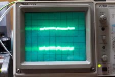
I hooked up the amps to the scope, it's set to 5mS resolution.
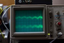
The first two have the servo disabled and sub-sonic filter out with scope set to 2mV/division. In the second pic I think the spikes you can see are what I thought was RF interference when I connected the TT.
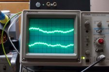
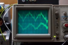
The second two are with the servo and 20dB gain on the in the final stage with the scope at 2mV for the 3rd picture and 5mV/division for the last one. In this amp the Servos are keeping the DC < 1mV so appear to be working.
I also upped the servo caps to 1uF. After removing the original caps I noticed how difficult it was to clear the solder from the pad connected to the ground plane (I had to heat it for about 20 secs to melt the solder left in the hole). So I wonder whether a dry joint to the ground might have been the origin of the servo problem.
It'd be good to work out what that interference is when I plug the TT in though... any ideas?
Thanks.
The first two have the servo disabled and sub-sonic filter out with scope set to 2mV/division. In the second pic I think the spikes you can see are what I thought was RF interference when I connected the TT.
The second two are with the servo and 20dB gain on the in the final stage with the scope at 2mV for the 3rd picture and 5mV/division for the last one. In this amp the Servos are keeping the DC < 1mV so appear to be working.
I also upped the servo caps to 1uF. After removing the original caps I noticed how difficult it was to clear the solder from the pad connected to the ground plane (I had to heat it for about 20 secs to melt the solder left in the hole). So I wonder whether a dry joint to the ground might have been the origin of the servo problem.
It'd be good to work out what that interference is when I plug the TT in though... any ideas?
Thanks.
Attachments
Last edited:
Let me first try to understand what I see.I hooked up the amps to the scope, it's set to 5mS resolution.
The first two have the servo disabled and sub-sonic filter out with scope set to 2mV/division. In the second pic I think the spikes you can see are what I thought was RF interference when I connected the TT.
The second two are with the servo and 20dB gain on the in the final stage with the scope at 2mV for the 3rd picture and 5mV/division for the last one. In this amp the Servos are keeping the DC < 1mV so appear to be working.
I also upped the servo caps to 1uF. After removing the original caps I noticed how difficult it was to clear the solder from the pad connected to the ground plane (I had to heat it for about 20 secs to melt the solder left in the hole). So I wonder whether a dry joint to the ground might have been the origin of the servo problem.
It'd be good to work out what that interference is when I plug the TT in though... any ideas?
Thanks.
T
he two traces on your scope images are for the right and the left channel simultaneously in one image, right ?
The good thing is that L and R are more or less the same in all images.
What can't be seen is the DC voltage, so whether the Servo is working or not is impossible to see.
But do I understand correctly that in all settings with servo, DC output is ca. 1mV ?
Your TT is picking up a 100Hz signal with spikes. this can easily be caused by mains pollution from refrigerators or whatever household appliance and doesn't look very alarming.
You mentioned to have some other Riaa amp, try to do the same measurement with the TT connected, and see if there is a difference.
And last but not least, is your amp encapsulated in a metal box, properly grounded to main earth and what about connecting your TT to main earth ?
Hans
- Status
- This old topic is closed. If you want to reopen this topic, contact a moderator using the "Report Post" button.
- Home
- Source & Line
- Analogue Source
- Phono Stage PCB Layout