zilog said:I have a running UcD prototype using 2n5551, 2n5401, 2n3906, 2n3904 and BC640 etc.
how can you have a running UcD when our expert has insisted many times over that the phillipse design didn't work?
")
Great to hear your success. It does make me wonder just how much current is needed to run the mosfets.
I dont have the completed schematic ready yet as I begun with something long time ago (I think it was a schematic released by classd4sure), and over time it has evolved into using other transistors, other resistance values, incorporatign protection etc, but in large it works the same way as the app note with small modifications.
The thing runs at 450-550 kHz in idle, the exact frequency depending on how much cross conduction I allow in the output stage.
I guess I will have a schematic in a couple of weeks as I will need to computerize it to allow the design of my next PCB.
Here is a picture of my ugly and EMI-horrible design
http://zilog.dyndns.org:8080/lagenheten/protect1.jpg
lumanauw said:Hi, Zilog,
With ordinary To-92 transistors, what is the switching frequency? Can it reach 400-500khz?
I haven't found the particular gate driver to limit switching frequency as the transistors I use (FDP3682) are so easy to drive. Actually I have been forced to slow turn-on down as being too fast here causes excessive hard-switching over the still conducting mosfets when the load is high. The only thing I want to improve here (apart from taking less space with smd:s) is faster turn-off using a FZT790A instead of the BC640 I am using for turn-off today.
zilog said:Here is a picture of my ugly and EMI-horrible design
http://zilog.dyndns.org:8080/lagenheten/protect1.jpg
I like your water bath dummy load! Nice work on the amp too
zilog said:
I haven't found the particular gate driver to limit switching frequency as the transistors I use (FDP3682) are so easy to drive. Actually I have been forced to slow turn-on down as being too fast here causes excessive hard-switching over the still conducting mosfets when the load is high. The only thing I want to improve here (apart from taking less space with smd:s) is faster turn-off using a FZT790A instead of the BC640 I am using for turn-off today.
zilog,
you mean to say BC640 are much faster than 2907? at least thats what I use to drive the mosfets...
RX5 said:
zilog,
you mean to say BC640 are much faster than 2907? at least thats what I use to drive the mosfets...
I used what I could get in shops here, havent given the 2907 any thought.
zilog,
ok ... well 2222/2907 are fast switchers..
anyway, regarding the UM10155_1 pdf, I can see that the mosfet driver/s use different transistors for the -ON- and -OFF-
BC857 // PBSS5140T....
does it really need to be "slow" to turn -off- mosfets??? like fast turn -ON- and slow turn -OFF- ???
confused...
RX5 said:zilog,
ok ... well 2222/2907 are fast switchers..
anyway, regarding the UM10155_1 pdf, I can see that the mosfet driver/s use different transistors for the -ON- and -OFF-
BC857 // PBSS5140T....
does it really need to be "slow" to turn -off- mosfets??? like fast turn -ON- and slow turn -OFF- ???
confused...
I have only looked at turn-on time for the turnoff-BJTs as they turn on to remove gate charge. In the UcD style driver, the turnoff-BJT never goes into saturation, and will therefore not fight the turnon-BJT too much at the next cycle.
The reason I have chosen the FZT790A over other BJTs is the combination of high gain and high Ic max. Since you want to turn off the mosfets as fast as possible, I think the BJT doing this needs to be rugged.
RX5 said:ok.. but still confused..
you mean like the TURN-ON BJT should be the "switching" types ... and the TURN-OFF can be any rugged//slower types??
or the reverse??
I can see in the datasheet the PBSS5140T are not "switching" types.. but LOW Vce saturation only..
I picked the BJT with fastest turn-on, enough Ic capability and the lowest Vce possible for the off-state as I could find. For the on-state I wasnt that picky as I still would need to limit the turn on-speed to avoid too high cross conduction.
There are probably other things to consider aswell, but this is as far as my competence and knowledge reaches.
zilog said:
I picked the BJT with fastest turn-on, enough Ic capability and the lowest Vce possible for the off-state as I could find. For the on-state I wasnt that picky as I still would need to limit the turn on-speed to avoid too high cross conduction.
There are probably other things to consider aswell, but this is as far as my competence and knowledge reaches.
its ok zilog,
im still learning too... I think 2907 is ok for turn OFF BJT.. it has Vce of 800mA max.... rugged enough??? for the turn ON BJT, I think i will use the BC857.. it is a switching transistor...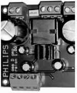
My UCD180s have an inductor marked EP17, which appears to be a Ferroxcube former.
Trouble is, there are several types of EP17, so it's difficult to know which core material they've chosen.
My Philips Demo PCB seems to have the same output inductor fitted - I'll see if there's any way of identifying it further.
Trouble is, there are several types of EP17, so it's difficult to know which core material they've chosen.
My Philips Demo PCB seems to have the same output inductor fitted - I'll see if there's any way of identifying it further.
Good news and bad news -
I've taken the inductor off the Philips pcb, and removed the spring - that's the good news!
The two halves of the ferrite are secured together with some kind of glassy epoxy resin - both at the centre, and at the edges. There's no way I can see of separating them without destroying the whole shielding, and probably the core.
There appears to be a single winding, of which I count 11 turns. Both connections are at the same end, so I would guess that there are two layers (possibly more - I can't see!!)
Gauge of wire? - I estimate 22swg ( sorry USA members, I'm an old fashioned Brit! - you'll have to do your own conversion to awg )
Number written on the spring --310421815671 / 0504K
Means nothing to me????
BTW, number written on the UCD 180 inductor is 'EP-17 30uH 180W -- 0619K'
And before you ask, no I'm not taking that one apart!
I've taken the inductor off the Philips pcb, and removed the spring - that's the good news!
The two halves of the ferrite are secured together with some kind of glassy epoxy resin - both at the centre, and at the edges. There's no way I can see of separating them without destroying the whole shielding, and probably the core.
There appears to be a single winding, of which I count 11 turns. Both connections are at the same end, so I would guess that there are two layers (possibly more - I can't see!!)
Gauge of wire? - I estimate 22swg ( sorry USA members, I'm an old fashioned Brit! - you'll have to do your own conversion to awg
)Number written on the spring --310421815671 / 0504K
Means nothing to me????
BTW, number written on the UCD 180 inductor is 'EP-17 30uH 180W -- 0619K'
And before you ask, no I'm not taking that one apart!
rogs said:Good news and bad news -
I've taken the inductor off the Philips pcb, and removed the spring - that's the good news!
The two halves of the ferrite are secured together with some kind of glassy epoxy resin - both at the centre, and at the edges. There's no way I can see of separating them without destroying the whole shielding, and probably the core.
There appears to be a single winding, of which I count 11 turns. Both connections are at the same end, so I would guess that there are two layers (possibly more - I can't see!!)
Gauge of wire? - I estimate 22swg ( sorry USA members, I'm an old fashioned Brit! - you'll have to do your own conversion to awg
Number written on the spring --310421815671 / 0504K
Means nothing to me????
BTW, number written on the UCD 180 inductor is 'EP-17 30uH 180W -- 0619K'
And before you ask, no I'm not taking that one apart!
rogs,
many thanks for that info... I WAS right all along.. its a singe layer no doubt
im guessing center AIR gap is between 0.8mm-1.5mm..an LC meter is REALLY helpfull if building one though..
Cheers,
Raff
- Status
- This old topic is closed. If you want to reopen this topic, contact a moderator using the "Report Post" button.
- Home
- Amplifiers
- Class D
- Philips UCD application note