Well, I can see your point since you have the talent to wind your own PS transformers. Wow! But for me it comes down to the first stage output having a voltage level that requires approx 1/4 (minus bias voltage) of the cathodyne PS. You are right that if you can do both direct coupling with that and match that 1/4 level then that is the ultimate. If you have any ideas for two tubes for doing that do not require wildly different PS voltages I'm interested. The other part of my problem was I like to keep the two channels separated within tubes and also like to use twin tubes to lower the tube count. I was never able to get there doing that. That's why I decided direct coupling had to go. It wasn't because I wanted to get rid of it.
1/4 + 3/4 bias gives (approximately) the biggest output voltage swing. It puts 1/2 rail across the cathodyne valve. Direct coupling to this puts only 1/4 rail across the previous valve. That is the problem: you can't have a good operating point on both stages with direct coupling from a common supply rail. The added resistor helps a bit by shifting everything up in voltage.exeric said:In my view it far more important to bias the cathodyne loads at the 1/4 and 3/4 point than it is to direct couple.
You don't get such a big problem with a direct coupled LTP phase splitter as that has gain so the previous stage needs much less anode swing so can cope with a slightly smaller anode voltage than a cathodyne feeder needs. However, both LTP and cathodyne have to be careful to avoid grid current as they both run the valve(s) with smallish anode-cathode voltage.
I prefer to have a capacitor between all stages and proper bias.
My experience is that the sound improves when inserting a capacitor before a directly coupled cathodyne or other stages.
The global feedback will cover largely the added capacitor distortions, especially in that design. A cathodyne should not drive powerful tubes which can draw grid current.
My experience is that the sound improves when inserting a capacitor before a directly coupled cathodyne or other stages.
The global feedback will cover largely the added capacitor distortions, especially in that design. A cathodyne should not drive powerful tubes which can draw grid current.
Theoretical capability
I decided to show what the theoretical capability of the cathodyne is, (pictures are worth a thousand words).
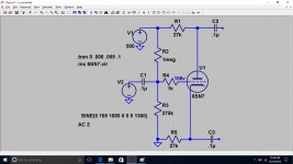
Here's the sim circuit biased at approx 1/4 rail voltage and 90v peak to peak output across each load (180 volts across both loads:
_
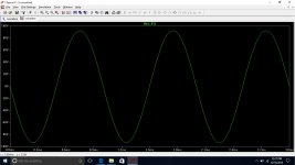
Here's the output waveform and the FFT of it at that level. Pretty good.
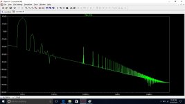
Notice that the first odd harmonic is over 80 db down. Most of the evens will cancel in the final stage.
Here is the waveform and the FFT for the same circuit driven at 50 P-P output:
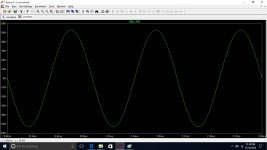
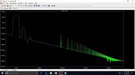
The FFT shows virtually distortionless phase splitting. You definitely won't be worrying about distortion in this stage. It's output is pristine. In all these waveform so far the waveforms look and act outstanding. The FFT almost would seem to not be needed because the correlation seems so good.
But wait...
Here's the same circuit biased at approx 1/3 rail voltage, instead of 1/4:
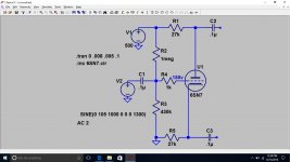
Here's the waveform and FFT for a 60 volt output.
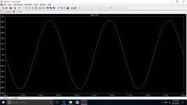
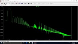
Visually the signal out looks pretty good until you look at the FFT for it. It's pretty horrible. The reason is because the higher odd harmonics are much more objectionable as you go higher. (Don't worry about the 100khz spikes in all of the FFT plots. I think they are just a spurious anomaly.) Also I couldn't get close to 90 the volt P-P output without flat topping so I just left it out. Even with the decreased drive it doesn't look close to the 50 volt PP when the cathodyne is biased at 1/4 rail voltage.
I decided to show what the theoretical capability of the cathodyne is, (pictures are worth a thousand words).
Here's the sim circuit biased at approx 1/4 rail voltage and 90v peak to peak output across each load (180 volts across both loads:
_

Here's the output waveform and the FFT of it at that level. Pretty good.


Notice that the first odd harmonic is over 80 db down. Most of the evens will cancel in the final stage.
Here is the waveform and the FFT for the same circuit driven at 50 P-P output:


The FFT shows virtually distortionless phase splitting. You definitely won't be worrying about distortion in this stage. It's output is pristine. In all these waveform so far the waveforms look and act outstanding. The FFT almost would seem to not be needed because the correlation seems so good.
But wait...
Here's the same circuit biased at approx 1/3 rail voltage, instead of 1/4:

Here's the waveform and FFT for a 60 volt output.


Visually the signal out looks pretty good until you look at the FFT for it. It's pretty horrible. The reason is because the higher odd harmonics are much more objectionable as you go higher. (Don't worry about the 100khz spikes in all of the FFT plots. I think they are just a spurious anomaly.) Also I couldn't get close to 90 the volt P-P output without flat topping so I just left it out. Even with the decreased drive it doesn't look close to the 50 volt PP when the cathodyne is biased at 1/4 rail voltage.
Last edited:
Here's the sim circuit biased at approx 1/4 rail voltage and 90v peak to peak output across each load (180 volts across both loads:
Oops, should be 180v peak to peak and 360 v peak to peak differential across both upper and lower loads.
I should mention my own conclusions about the simulation. Others may have different conclusions. While no simulation can be exactly what would happen in the real circuit I think a few things are true.
1. If the outputs drive source followers the simmed results shouldn't be appreciably compromised because there would be so little current drawn that any difference in the impedances of the upper and lower loads wouldn't amount to any significant difference from the simmed results.
2. It's really important to bias the cathodyne close to 1/4 the rail voltage. It's important not just to maximize the signal output without flat topping, but also to minimize IM distortion. My personal opinion is that getting that right swamps any reason to direct couple. If you can do both fine. But have your priorities right.
3. A signal of 90volts output, 180 P-P, seems to me to be a lot to work with. If you need a lot of excess for feedback that's another matter. I generally do not care for high global feedback designs, so it works for me. Others can have legitimately different opinions about that.
Notice that the first odd harmonic is over 80 db down. Most of the evens will cancel in the final stage.
Wow, sounds interesting!
Do you mean most of even harmonics of the phase splitter will cancel in the final stage?
The cathodyne should be biased at less than B+/4 (for that stage). Exactly it is determined by the load line, both loads combined, and the plate voltage at which grid current begins is subtracted from B+ and that number is divided by 4. In practice this is closer to one fifth than one quarter.
cheers,
Douglas
cheers,
Douglas
Wow, sounds interesting!
Do you mean most of even harmonics of the phase splitter will cancel in the final stage?
Yeah, maybe I got that wrong. But if you're right then my simulation would show that a cathodyne will have a totally different harmonic signature from an LTP phase splitter. It that was correct it would be interesting and not necessarily bad. More like an SE.
Last edited:
Yeah, maybe I got that wrong.
You just wanted too much, too easy. ;-)
I decided to show what the theoretical capability of the cathodyne is, (pictures are worth a thousand words).
… ⅓ rail … Visually the signal out looks pretty good until you look at the FFT for it. It's pretty horrible. The reason is because the higher odd harmonics are much more objectionable as you go higher. (Don't worry about the 100khz spikes in all of the FFT plots. I think they are just a spurious anomaly.) Also I couldn't get close to 90 the volt P-P output without flat topping so I just left it out. Even with the decreased drive it doesn't look close to the 50 volt PP when the cathodyne is biased at ¼ rail voltage.
Seriously … just don't drive it at AC 105V … drive at 77V instead, and its FFT goes to a nice –80 dB (just like the ¼ rail case)
Or as the saying goes, “Changing 1 thing almost always requires rescaling other things…”
GoatGuy
The whole point, which I think you missed, was that I don't think the IM scales. It isn't distortion generated from clipping. There's lots of evidence that it happens from the asymmetry of the cathodyne operating point when outside the 1/4 and 3/4 biasing points on the upper and lower "loads". The grid biasing point is different from that and is nitpicking something that I never disputed. This has been documented elsewhere in this thread and other places, even historically. No one wants to believe it. That's their problem and your problem.
It's really strange to me that you can't see the obviousness of the asymmetry. On both the upper and lower resistor loads the asymmetry is the voltage difference between upper excursion reaching its limit and the lower excursion hitting its limit. It should be obvious that difference is a physical effect. The big question is why do you think that that difference in limit between upper and lower excursion does not have physical effects that show up in distortion? Remember, those excursions are inverse to each other. You will have much more crowding to the middle than to the ends on both upper and lower resistor voltages in 1/3 2/3 load biasing. There is no reason that shouldn't have effects well before actually running into each other unless one doesn't have the imagination to see it.
Last edited:
If 2 resistors of the same value are in series, what differences in a voltage drop can cause current on each of them?
I don't mean when grid current adds visibly to the current through the cathode resistor.
And I don't mean load of the phase splitter on non-linear grids of output tubes through capacitors, I mean just the phase splitter per se.
I don't mean when grid current adds visibly to the current through the cathode resistor.
And I don't mean load of the phase splitter on non-linear grids of output tubes through capacitors, I mean just the phase splitter per se.
- Status
- This old topic is closed. If you want to reopen this topic, contact a moderator using the "Report Post" button.
- Home
- Amplifiers
- Tubes / Valves
- phase splitter issue