I do not believe that an increase in the potential of the cathodyne's cathode will affect the voltage at its grid.
????
I am affraid we are not living on the same planet
Jacques
Last edited by a moderator:
????
I am affraid we are not living on the same planet
Jacques
It will help when the tube saturates to restore some voltage potential and prevent more serious tube cut off. Prevents the cathode from seeing a 0V.
During normal operation the true cathode voltage would be higher than 50V.
I do not believe that an increase in the potential of the cathodyne's cathode will affect the voltage at its grid.
True, to a first approximation. Of course, if you feed extra current into the cathodyne cathode resistor, the cathodyne tube will try to maintain the same voltage at the cathode and will back off on its own contribution to the current through the cathode resistor. This will have a tiny effect on the Vg-k of the cathodyne tube. We're talking tiny, though.
Edit: Nevermind, that's only a change in Vg-k, not what you were talking about. Vg to ground can only be affected if tube grid starts drawing significant current, which is clearly not what is happening in this circuit.
Last edited:
It will help when the tube saturates to restore some voltage potential and prevent more serious tube cut off. Prevents the cathode from seeing a 0V.
During normal operation the true cathode voltage would be higher than 50V.
I am having so much trouble making sense of this. You talk of saturation and cutoff as if they coincide in some way. They are at opposite ends of the swing. Saturation is max current, cutoff is zero current.
It is true that the cathode cannot reach ground potential with the 330k resistor (it is restricted to approximately +42V), but I am still unclear as to why that would be an advantage. The output stage would have been seriously overdriven well before that happens. Why is keeping the cathode from swinging to ground desirable?
I repeat my opinion stated #1155 because there is a big misunderstanding somewhere.
IF you inject more cuurent in the Rk, through 330k resistor, the voltage of the cathode to the ground will be higher.
Consequently the voltage of its grid to ground will be higher.
This allows to use a higher voltage (to ground) for the plate of the preceeding tube (80V instead of 50V for exemple).
Jacques
IF you inject more cuurent in the Rk, through 330k resistor, the voltage of the cathode to the ground will be higher.
I don't agree, there is very strong feedback there. If you inject more current in Rk, the tube will compensate by putting less of its own current into Rk and the voltage of the cathode to ground will stay approximately the same.
This will, however, have a much stronger effect on the idle voltage at the plate of the cathodyne.
You are right SpreadSpectrum,
It is obvious that when the tube recovers from a complete voltage swing the 50V potential will reappear (or 42 as you calculated) faster than the tube time to recover from cutoff and not saturation.
I think this helps in allowing less distortion and a quicker recovery while limiting grid current in such an event.
In order to cancel more power supply ripple noise in the cathode output I think the 330k does nothing but make it worse.
To do it correctly you should have a matching network from the power supply to the input grid and another network directly from the anode to the cathode output.
I think we are experiencing a collective problem in communication.
The one point I would like to reiterate is the one I made in post 1156. The DC grid voltage of the cathodyne is set by the DC voltage established at the plate of the triode which drives that grid. Increasing the cathodyne's cathode's DC voltage will not affect the voltage at its grid (assuming of course that this does not exceed the tube's maximum cathode-grid voltage).
The one point I would like to reiterate is the one I made in post 1156. The DC grid voltage of the cathodyne is set by the DC voltage established at the plate of the triode which drives that grid. Increasing the cathodyne's cathode's DC voltage will not affect the voltage at its grid (assuming of course that this does not exceed the tube's maximum cathode-grid voltage).
The extra resistor allows the phase splitter cathode to sit at a higher voltage while still maintaining the desired valve current (set from the chosen bias point) and impedance balance (needed for cathodyne operation). It doesn't set the grid voltage, it reacts to the grid voltage. It doesn't set the cathode voltage either. Basically the resistor allows the PS to fit into a limited supply rail and still have enough voltage swing at cathode and anode.
So I agree with SpreadSpectrum on this.
However, an unfortunate side effect is that the PS current changes more quickly with anode voltage variations from the previous stage so it might make the design more sensitive to problems with different valve samples or as they age. Electronics always involves compromise.
I believe post 1094 shows how to equalize supply noise in the outputs of a cathodyne with perfectly matched loads. This would lead to noise cancellation by a perfectly balanced output stage.
But output stages are not perfectly balanced. So add a pot in series with the resistor from the supply to the gain stage cathode in that post and retain the "Fischer pot" in series with the cathodyne's cathode load. Tweak both to arrive at supply noise cancellation and a well-balanced output stage.
But output stages are not perfectly balanced. So add a pot in series with the resistor from the supply to the gain stage cathode in that post and retain the "Fischer pot" in series with the cathodyne's cathode load. Tweak both to arrive at supply noise cancellation and a well-balanced output stage.
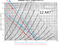
I finally drew some load lines and confirmed that the reason for the 330k resistor is to create a good operating point for the cathodyne. Operating point does not look good (too close to Vg=0 line) at more than 2mA (what it would be without the 330k resistor). Dropping the operating point by ~2/3 of a mA (which the 330k resistor does) makes things much better. The 330k is meant as a fix to create a good DC operating point, not as something to inject ripple for cancellation in the output stage (which it wouldn't be very good at anyway, due to its large value).
This has me wondering how my amp that has this resistor removed works as well as it does (it sounds just fine). I assume it must be swinging the cathodyne grid somewhat positive. Maybe I should put that 330k resistor back in.
This has me wondering how my amp that has this resistor removed works as well as it does (it sounds just fine). I assume it must be swinging the cathodyne grid somewhat positive. Maybe I should put that 330k resistor back in.
Last edited:
Doesn't the setting of R83 overwhelm the effect of the 330k resistor?
Sort of. Conditions are such that there is no way to get AC balance and a good operating point without the 330k resistor, given the supply rail and DC grid voltage imposed by the previous stage on the cathodyne.
The 330k resistor is a Band-Aid fix to make the DC conditions work out. Draw some load lines and it will all make sense. Actually, you don't even have to draw the lines, just plot the DC operating points with and without the 330k resistor.
Things would work out better if DC grid voltage were lower on the cathodyne, but I suspect that running the previous stage at a plate voltage that was 30V or so lower would create similar problems for that stage.
This is part of the reason that I use LTPs.
That pot setting is the difference between drawing 1.3 and 3.7mA, assuming a cathode voltage of 100V as shown on the schematic. I'll take your word that the value of the 330k is apparent if you draw some load lines, but I find that surprising considering the effects of the pot.
That pot setting is the difference between drawing 1.3 and 3.7mA, assuming a cathode voltage of 100V as shown on the schematic. I'll take your word that the value of the 330k is apparent if you draw some load lines, but I find that surprising considering the effects of the pot.
Sure, you can crank the pot to get to a workable operating point (one that doesn't require positive grid voltages) but it won't give you good AC balance at the same time. The 330k resistor makes it possible to get both with 100V on the grid.
Sure, you can crank the pot to get to a workable operating point (one that doesn't require positive grid voltages) but it won't give you good AC balance at the same time. The 330k resistor makes it possible to get both with 100V on the grid.
Well, now I feel a bit silly because it just occurred to me that you could easily just increase the resistance of both the anode and cathode resistors and accomplish the very same thing. So now I am back to not seeing any good reason for the 330k resistor again.
Here's what I get for the load lines with and without the 330K resistor and the operating points at the extreme settings of R83. Unless I miscalculated, a good portion of the pot range will lead to grid current being drawn. And in comparison to the pot settings, the effects of the 330k resistor seem small.
In my opinion, it should have been designed to preclude the possibility of grid current being drawn.
In my opinion, it should have been designed to preclude the possibility of grid current being drawn.
Attachments
I believe post 1094 shows how to equalize supply noise in the outputs of a cathodyne with perfectly matched loads. This would lead to noise cancellation by a perfectly balanced output stage.
But output stages are not perfectly balanced. So add a pot in series with the resistor from the supply to the gain stage cathode in that post and retain the "Fischer pot" in series with the cathodyne's cathode load. Tweak both to arrive at supply noise cancellation and a well-balanced output stage.
I don't know if you tried this in reality and observed positive results.
Two pots, one on the feedback noise and one on Rk seems not helping. Simply increasing feedback will lower your power supply noise regardless of Rk balance or your solution to place a resistor from power supply to feedback, which I saw in many amplifiers.
I found on the Valve Wizard. uk site that during power up before conduction the directly coupled cathodyne can arc because the grid raise up to B+ and exceeds grid-cathode max V.
The 330k can help in this regard with grid-cathode potential arcing when amp is powered On.
Simply increasing feedback will lower your power supply noise regardless of Rk balance
Agreed. But so will the Post 1094 scheme. Simulate it, and you'll see.
I found on the Valve Wizard. uk site that during power up before conduction the directly coupled cathodyne can arc because the grid raise up to B+ and exceeds grid-cathode max V.
The 330k can help in this regard with grid-cathode potential arcing when amp is powered On.
Yes, but only to a very small extent. If arcing is an issue, the 330k resistor is nowhere near a panacea.
- Status
- This old topic is closed. If you want to reopen this topic, contact a moderator using the "Report Post" button.
- Home
- Amplifiers
- Tubes / Valves
- phase splitter issue