CPaul noted a problem with my graph. Looking again I see that I was using 20k/200R as the limits of the load resistances, not 10k/100R.
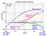
Altogether I made a bit of a mess of it, didn't I! OK, Here is the corrected corrected version. I also added the 'effective' output impedances to show how they converge when Ra = Rk.
An externally hosted image should be here but it was not working when we last tested it.
Now when Ra=Rk, Ra and Rk are 2000 ohms each; is this correct?
Is either the Anode output Z, or the effective Anode output Z equal to the plate to ground impedance?
I have shown the driving point impedance to anode and cathode on my plot as the blue and green curves. These are the impedances taken one at a time from anode or cathode to ground.
With the value of Ra and Rk each being 2000 ohms when Ra/Rk=1, I get a slightly different graph:
Attachments
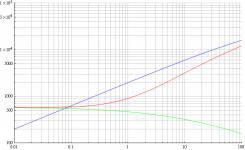
My results track those of The Electrician exactly. I show the equations I used and the calculations performed by MathCad in the attachment.
I am particularly suspicious of the value Merlin shows for anode output impedance when Rk = Rp = 2K. How can the impedance across a 2K resistor be about 10K? There are also much smaller deviations between Merlin's and our results for differential and cathode impedances in the range where Rp/Rk goes from 1 to 10.
I would appreciate it if Merlin would post the equations for and discuss what he calls 'effective' impedance. I'm not familiar with that term.
Now when Ra=Rk, Ra and Rk are 2000 ohms each; is this correct?
No, when Ra=Rk they are both 10k. Then it steps in 1k increments down to 1k, and then a final 200R value just so the graph plots nicely on logarithmic axes.
Ah! I see what happened. We chose different sets of Rk and Rp points ro graph, although our endpoints were the same. That explains things.
I've updated my graph to show the values of Rp and Rk that The Electrician and I used, with Rp = Rk = 1k at the center point. Merlin's selection of values had Rk = Rp =10K in the center.
Merlin, could you post an updated version of your graph which shows the values of Rp and Rk that you selected? No doubt your results are good for your values, but it's a little unclear, at least to me, what they are.
Also, could you please explain and post equations for "effective" impedances?
Thanks.
Graph updated. I set the limits at 10k this time since it's probably easier to think in tens, and it plots nicer too.Merlin, could you post an updated version of your graph which shows the values of Rp and Rk that you selected?
Also, could you please explain and post equations for "effective" impedances?
Zdiff = ra(Ra+ Rk) / [ra + Ra + Rk(mu+1)]
Za = 1 / [ 1/Ra + 1 / (ra + Rk(mu+1)) ]
Zk = 1 / [ 1/Rk + (mu+1)/(ra+Ra) ]
The 'effective' output impedances are simply the differential output impedance divided in the same ratio as the two load resistances.
Za(effective) = Ra.Zdiff / (Ra+Rk)
Zk(effective) = Rk.Zdiff / (Ra+Rk)
Last edited:
Thanks, Merlin. I don't know if it's my browser or what, but if you updated post 879, I still can't open that graph. Maybe SY can help again?
I see how you calculated the 'effective' output impedances. Is there some way to measure them directly? Do they have some practical value?
I see how you calculated the 'effective' output impedances. Is there some way to measure them directly? Do they have some practical value?
When anode and cathode loads are same and linear,
cathodyne splits exactly even, no problem... Does
not matter anode and cathode impedance are same
or different. Only differential impedance is in play.
But when loads are not linear, cathodyne fails due
to coupling caps pumping in opposite directions.
(One toward the center, one toward the rail). Now
impedance mismatch might aggravate this situation,
but even a forced perfect match does not fix it.
The problem with cathodyne applied to situations
where it legitimately should not work properly,
is nothing to do with A/K impedance mismatch.
Waste our time arguing the wrong questions...

In #55, I showed how to make impedance equal, and proved
it does nothing useful (except give Mu/2 gains and very low
equal impedance) because you still can't drive grid current...
In #160, Wb showed how to drive grid current without adding
followers, though the unequal impedance is still there in his
circuit, I think....
These two ideas need to be combined and see what happens.
I have a feeling that DC on the plate side of the coupling cap
still wanders, but maybe Mu/2 would keep that in check?
Last edited:
Nevermind. Cathode responsible for supplying DC to both output grids
just makes plate voltage pull inward (toward a clipping point at center)
twice as fast.
Combining #55 with #160, only makes both mistakes worse.
A pair of followers still seems the most straightforward answer...
just makes plate voltage pull inward (toward a clipping point at center)
twice as fast.
Combining #55 with #160, only makes both mistakes worse.
A pair of followers still seems the most straightforward answer...
I didn't understand how that was supposed to work. I was about to sim it. I still may to better understand it.
I agree about a pair of followers. I thought maybe it would be good for them to be low mu, since this tends to push the grid bias more negative, giving the design more headroom before the followers draw grid current.
Another nice thing about YvesM's circuit is its opportunity for fully differential operation. With a nice current source for the input diff pair, the design should have excellent CM and PSRR. In addition, if the input stage pentode screens are tied together, I suspect that their decoupling cap might not be needed, and if it is, it shouldn't insert a zero/pole pair into the design.
Your thoughts?
By the way, I think there is room here to pursue both discussions on DC bias current-pumping and Cathodyne operation. It's important to set the record straight on the latter, with some still clinging to a model that misleads. (Witness what it did to Dave Slagle's specification.) I'll continue to try to point out problems with the equal-Z model. But that shouldn't stop other discussions.
With a nice current source for the input diff pair, the design should have excellent CM and PSRR. In addition, if the input stage pentode screens are tied together, I suspect that their decoupling cap might not be needed, and if it is, it shouldn't insert a zero/pole pair into the design.
Your thoughts?
Yes, this was quite a common topology for DC amplifiers- pentode LTP with screens tied together, no need for decoupling, CF drivers, etc.
Various combinations of balanced or push-push feedback were employed.
A constant-current source in the tail was standard practice, although for maximum CMRR the tail needs a finite impedance, not an infinite one, so the first LTP in the circuit may use a simple resistor tail.
Because mu is non-linear. I can't remember the algebra off the top of my head, but the result is that you can obtain essentially infinite CMRR from a long-tailed pair, but only when the tail resistance is finite (a few hundred k-ohms usually), which is perhaps counter intuitive. A near-perfect CCS tail gives you perfect AC balance, but only finite CMRR; you can't maximise both at the same time. So in the vintage DC amplifiers you see different sorts of tail depending on what the designer was trying to achieve. Doesn't matter as much for audio.Why does it need a finite impedance?
Post #879. If you can't see an image you should still see a link?Where was your graph with the Rp and Rk values posted?
They're not REALLY useful. You can use them to find the bandwidth, but only if the capacitive loads are in the same ratio as the resistive loads (e.g., post #786), which is unlikely except for the usual balanced condition.Would you kindly answer my questions about effective impedances?
Last edited:
...unlikely except for the usual balanced condition.
LOL!
- Status
- This old topic is closed. If you want to reopen this topic, contact a moderator using the "Report Post" button.
- Home
- Amplifiers
- Tubes / Valves
- phase splitter issue