Your circuit which purportedly tests P & K to ground impedances by simultaneously shorting plate and cathode to ground draws no ground current. So there can be no current through ground referenced impedances. So they can't possibly be tested by your circuit.
I can't answer a nonsequitur.

Every test you have proposed to prove unequal plate and cathode impedances has unbalanced the loads. I do not accept braking the model to prove it wrong acceptable.
To test an impedance, you run a current through it, observe the resulting change in voltage across it, and divide. Since the impedances in question are connected to ground, as you test each one individually, the current must go into ground from one path and out through another. There simply is no other way to test the impedance. If that's all it takes to break the model, it's a pretty brittle model. But I think you find your way through this a little later on in this post.
In the case of the dual LCR's the only correct answer is ~5800 ohms in both the plate and cathode...
I agree in this case there will be no current flowing through the ground node. I will also accept that we need to call this the differential output impedance.
The problem was the demand, per SY's grounded two source model, that each load be driven by a separate source of impedance 6K rather than a single differential source of impedance 12K.
I think the key here is to draw the current loops and treat each loop impedance as it should. Currents common to the plate and cathode must have the differential output impedance. Currents common to just the plate or cathode loop (through ground) will have the respective plate or cathode impedance.
Dave, I agree completely. Not sure I could have said it better myself. (SY, take note!) Consensus is nice!
The problem was the demand, per SY's grounded two source model, that each load be driven by a separate source of impedance 6K rather than a single differential source of impedance 12K.
here is where I have a problem. The only way for the circuit to provide the proper results is with 5800 ohms in the plate side and 5800 ohms in the cathode side. This suggests that the differential output impedance of the cathodyne is 200 ohms to make up the needed 12K impedance.
If it were just the differential output impedance that we care about, you should be able to divide up that 11K8 series resistance any way you want and still get the 12K differential output impedance, when you do this the low frequency behavior tells us we are not providing the proper source impedance.
dave
I understand why this bothers you.
The best simple answer I can think of is that the Cathodyne is a bit more complex than either a single floating differential source or certainly a pair of ground-referenced opposing sources. That’s one good reason not to think of it in terms of either of these models, because doing so is sure to trip you up.
To get an understanding of a circuit, I always recommend doing a full circuit analysis rather than assuming shortcut models. Short of that, you could play around with a lot of simulations, but I still prefer the former approach.
Has anyone ever built a concertina phase splitter and have the signal be perfectly split but they differed in amplitude?
I had that happen is when I used too small of a grid stop resistor on the input of the splitter.
And another time I tied too many output tubes in parallel. I increased the grid stoppers on the output which did fix it however, I went back and added a 6sn7 as a buffer between the outputs and phase splitter to provide a better drive signal.
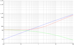
I thought it might be interesting for any lurkers to see what happens to the differential output impedance (Zak) as you gradually unbalance the cathodyne. This graph shows an example for an ECC83 / 12AX7 as the anode load (Ra) is varied from 20k down to 100ohms, while the cathode load (Rk) is simultaneously varied from 100ohms up to 20k.
Starting inthe middle where the loads are equal (Ra/Rk=1), the differential output impedance is roughly equal to the cathode output impedance.
Reducing Ra has only a small effect on the differential output impedance, whereas reducing Rk causes a large increase in Zak.
In the limits Zak becomes equal to Za or Zk.
An externally hosted image should be here but it was not working when we last tested it.
Last edited:
You're right, that should be 10k and 100ohms. The 20k bit goes off the end of the graph!Also, I'm a little confused by the x axis. If Ra/Rk = 100, I don't think Ra could be 20K while Rk is 100ohms.
Thanks.
An externally hosted image should be here but it was not working when we last tested it.
The equations are the usual ones- they've been posted plenty of times already.
Last edited:
When you post a graph like this it would be a great help to those who would like to duplicate your result if you would state explicitly the values you used for rp, u and any other relevant parameters, rather than just saying "This graph shows an example for an ECC83 / 12AX7".
What values did you use for the relevant parameters?
What values did you use for the relevant parameters?
They were written on the first graph, but I forgot to add them to the corrected version. They were:What values did you use for the relevant parameters?
mu = 100
ra = 60k
Last edited:
I get a substantially different result. When Ra/Rk = 1, Ra=1000 and Rk=1000. When Ra=1000 ohms, how can the anode output Z be as great as 10000 ohms?
Even though, as you say, "The equations are the usual ones- they've been posted plenty of times already.", it might help track down the source of the difference between my result and yours if you would post the equations you used to generate your plot.
I didn't use derived equations, but rather just solved the admittance matrix for the Cathodyne numerically.
I used the same colors you used for the 3 impedances.
Attachments
CPaul noted a problem with my graph. Looking again I see that I was using 20k/200R as the limits of the load resistances, not 10k/100R.
Altogether I made a bit of a mess of it, didn't I! OK, Here is the corrected corrected version. I also added the 'effective' output impedances to show how they converge when Ra = Rk.
Altogether I made a bit of a mess of it, didn't I! OK, Here is the corrected corrected version. I also added the 'effective' output impedances to show how they converge when Ra = Rk.
An externally hosted image should be here but it was not working when we last tested it.
- Status
- This old topic is closed. If you want to reopen this topic, contact a moderator using the "Report Post" button.
- Home
- Amplifiers
- Tubes / Valves
- phase splitter issue