Bob Cordell said:
Hi Brian,
I like it. It is much the same as the balanced input circuit I have been using for some time that I described over in the Unipolar vs Complementary input stage thread (page 8, post 199).
In that circuit, I used it outside the loop as a differential buffer to provide a nice hi-impedance balanced input for an amplifier. You are using a similar circuit inside the loop to drive the bipolar input stages.
My circuit uses a differential pair to form a differential CFP function. I call the whole thing a Differential Complementary Feedback Quad (DCFQ).
The circuit as shown in the original post along with a VAS to make a balanced input amplifier is shown below.
Being in the open loop, and connected as shown, its THD is less than 0.002% under all input driving conditions.
Cheers,
Bob
Hi Bob.
Nice circuit. People usually call me Glen though

Cheers,
Glen
G.Kleinschmidt said:
Hi Bob.
Nice circuit. People usually call me Glen though
Cheers,
Glen
Eeeeks! I'm soo sorry! My apologies.
Cheers,
Bob
Re: Re: fighting VAS
Hi Glen,
I actually liked the simulation experiment you did to investigate the Fighting VAS issue. You introduced REALLY big asymmetries and saw significant THD increases, but increases that, when put in the perspective of the big asymmetries, were not terrible.
I also agree that the THD alone doesn't tell us they are not fighting, but maybe the unseen common mode fight is not causing a lot of trouble. Anyway, I do think the VAS Fighting thing is something to be concerned about, but that its bad effects may be very dependent on the particulars of the amplifier.
For me, I'll probably stick with the unipolar stage and a JFET input stage, and I'll always be curious about what real, objective benefits the full-complementary approach brings to the table that cannot be had with a unipolar approach. Someone on the other side of the fence could just as easily say "what are the real, objective benefits that a JFET input stage brings to the table that cannot be had with a bipolar input stage".
Cheers,
Bob
G.Kleinschmidt said:
Hi Edmond.
Don’t take my words the wrong way either
I agree that just looking at the THD isn't enough to determine if the VAS's are really fighting or not, but the fact that it takes really big errors in voltage gain between the two halves of the circuit to make the THD go up considerably, as far as I'm concerned, for my design, “VAS fighting” is a practical non-issue.
You are trying to get the front end performance an order of magnitude better, your VAS’s have ~100 times lower Zout at 20kHz than mine, and that obviously comes with added difficulties which I don’t necessarily have to worry about in my design – please note; no criticism here.
Slew rate of my amp is what you would expect from a miller compensated amp with 34dB loop gain at 20kHz (I’ll see how much farther I can push this out in the real amp). I could make it higher by using a compensation scheme like that used in Bobs amp, but then I don’t get the OPS THD reduction produced by the TMC.
WRT clipping, I have refined and tested this on the 12W version and it is as good as any amp. I clamp the voltage at the VAS buffer bases to limit the peak VAS current to about 2-3 times the VAS Iq. In this design, I also clamp the voltage swing at the collectors of the VAS with a circuit that tracks the unregulated supply voltage of the OPS. This prevents the VAS trannies from saturating as well as the driver trannies.
Cheers,
Glen
Hi Glen,
I actually liked the simulation experiment you did to investigate the Fighting VAS issue. You introduced REALLY big asymmetries and saw significant THD increases, but increases that, when put in the perspective of the big asymmetries, were not terrible.
I also agree that the THD alone doesn't tell us they are not fighting, but maybe the unseen common mode fight is not causing a lot of trouble. Anyway, I do think the VAS Fighting thing is something to be concerned about, but that its bad effects may be very dependent on the particulars of the amplifier.
For me, I'll probably stick with the unipolar stage and a JFET input stage, and I'll always be curious about what real, objective benefits the full-complementary approach brings to the table that cannot be had with a unipolar approach. Someone on the other side of the fence could just as easily say "what are the real, objective benefits that a JFET input stage brings to the table that cannot be had with a bipolar input stage"
.Cheers,
Bob
Hi Edmond
In light of the fact that you guys are going to do some further development work on the OPS and OPS protection, here are a few things that I think are worth considering.
In a really high-end amplifier, it’s generally considered a desirable trait that the amplifier can drive difficult reactive loads with significant impedance dips without current limiting or distorting too much. For example, Halcro’s ~15A limit is a bit lame.
Suppose an amp is rated at 312W into 4 ohm. (50V peak / 12.5A peak). You might want an output stage that can deliver the full voltage swing into a 1-ohm load for brief bursts, or 50A peak.
To achieve this you simply need to parallel up enough output devices. There is a lot of merit to this approach, particularily WRT OPS protection - You can then protect such a stage from short circuit destruction with a current limiter at 50A or a circuit that will simply shut the whole amp down if such a current is exceeded for even an instant or a specific duration.
Such an amp could be made almost indestructible, and you wouldn’t have to worry about the protection circuitry incurring sonic degradation because it simply doesn’t operate under any normal operating current, even when driving exceptionally awful loads.
Take my 300W 4ohm OPS as an extreme example – I can deliver 100A peak without even entering the fT/beta droop area of the output BJT’s; with an output stage rendered practically indestructible with a protection circuit which shuts the amp down with the detection of 150A peak.
Cheers,
Glen
Re: Re: Re: fighting VAS
Thanks for the comments Bob.
I particularly like fully symetrical amplifiers because they make it easy to implement a really low distortion symmetrical VAS with bootstrapped cascoding.
Cheers,
Glen
Bob Cordell said:
Hi Glen,
I actually liked the simulation experiment you did to investigate the Fighting VAS issue. You introduced REALLY big asymmetries and saw significant THD increases, but increases that, when put in the perspective of the big asymmetries, were not terrible.
I also agree that the THD alone doesn't tell us they are not fighting, but maybe the unseen common mode fight is not causing a lot of trouble. Anyway, I do think the VAS Fighting thing is something to be concerned about, but that its bad effects may be very dependent on the particulars of the amplifier.
For me, I'll probably stick with the unipolar stage and a JFET input stage, and I'll always be curious about what real, objective benefits the full-complementary approach brings to the table that cannot be had with a unipolar approach. Someone on the other side of the fence could just as easily say "what are the real, objective benefits that a JFET input stage brings to the table that cannot be had with a bipolar input stage"
Cheers,
Bob
Thanks for the comments Bob.
I particularly like fully symetrical amplifiers because they make it easy to implement a really low distortion symmetrical VAS with bootstrapped cascoding.
Cheers,
Glen
Re: Re: fighting VAS
Hi Glen,
In general, you can't say that VAS fighting is a non-issue, as it depends entirely on the specific design details. When using a heavily downgraded VAS, its obvious that a 'non-VAS' makes it a non-issue.
BTW, the higher VAS-Zo, the lesser 'pole-splitting' by the VAS.
One important reason we opted for a fully complementary topology is that it opens the way to a more powerful VAS, that is, high current drive capability (75mA) and (essentially) no slew rate limiting. Therefor, using crippled VASes makes a fully complementary topology rather pointless.
Also, I like to point out that the primary reason for using a common mode control loop (CMCL) was not to solve the fighting VAS issue, rather to ensure a stable DC operating point (combined with high VAS gain).
As for clamping, I'm sure your setup is okay. In our design however, we had to walk a different path, as a simple clamp couldn't cope with the high drive currents of the NDFL stage. As Ovidiu already said "we sweated blood over the clipping circuitry in our amp". Indeed, it was a "tour de force". We finally ended with a "nested clamp". that acts not only on the VAS input, but also on the inverting input of the IPS (see D13,Q27a,D5,R25). Please, compare our clamping behavior with the original one of E.M. Cherry.
Cheers, Edmond.
G.Kleinschmidt said:Hi Edmond.
Don’t take my words the wrong way either
I agree that just looking at the THD isn't enough to determine if the VAS's are really fighting or not, but the fact that it takes really big errors in voltage gain between the two halves of the circuit to make the THD go up considerably, as far as I'm concerned, for my design, “VAS fighting” is a practical non-issue.
You are trying to get the front end performance an order of magnitude better, your VAS’s have ~100 times lower Zout at 20kHz than mine, and that obviously comes with added difficulties which I don’t necessarily have to worry about in my design – please note; no criticism here.
Slew rate of my amp is what you would expect from a miller compensated amp with 34dB loop gain at 20kHz (I’ll see how much farther I can push this out in the real amp). I could make it higher by using a compensation scheme like that used in Bobs amp, but then I don’t get the OPS THD reduction produced by the TMC.
WRT clipping, I have refined and tested this on the 12W version and it is as good as any amp. I clamp the voltage at the VAS buffer bases to limit the peak VAS current to about 2-3 times the VAS Iq. In this design, I also clamp the voltage swing at the collectors of the VAS with a circuit that tracks the unregulated supply voltage of the OPS. This prevents the VAS trannies from saturating as well as the driver trannies.
Cheers,
Glen
Hi Glen,
In general, you can't say that VAS fighting is a non-issue, as it depends entirely on the specific design details. When using a heavily downgraded VAS, its obvious that a 'non-VAS' makes it a non-issue.
BTW, the higher VAS-Zo, the lesser 'pole-splitting' by the VAS.
One important reason we opted for a fully complementary topology is that it opens the way to a more powerful VAS, that is, high current drive capability (75mA) and (essentially) no slew rate limiting. Therefor, using crippled VASes makes a fully complementary topology rather pointless.
Also, I like to point out that the primary reason for using a common mode control loop (CMCL) was not to solve the fighting VAS issue, rather to ensure a stable DC operating point (combined with high VAS gain).
As for clamping, I'm sure your setup is okay. In our design however, we had to walk a different path, as a simple clamp couldn't cope with the high drive currents of the NDFL stage. As Ovidiu already said "we sweated blood over the clipping circuitry in our amp". Indeed, it was a "tour de force". We finally ended with a "nested clamp". that acts not only on the VAS input, but also on the inverting input of the IPS (see D13,Q27a,D5,R25). Please, compare our clamping behavior with the original one of E.M. Cherry.
Cheers, Edmond.
Attachments
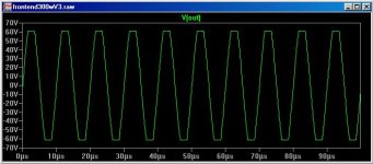
G.Kleinschmidt said:Me again
Clipping at 100kHz driving a 4 ohm load
Cheers,
Glen
Hi Glen,
Looks good!!!
> can send you another *.asc file.
Yes, please.
Cheers, Edmond.
Re: Re: Re: fighting VAS
Hi Bob,
I like to add that it was you who opened my eyes on this topic, about 9 month ago. Let's have look again, you too Glen, at this discussion:
http://www.diyaudio.com/forums/showthread.php?postid=1119659#post1119659
Cheers, Edmond.
Bob Cordell said:Hi Glen,
[snip]
I also agree that the THD alone doesn't tell us they are not fighting, but maybe the unseen common mode fight is not causing a lot of trouble. Anyway, I do think the VAS Fighting thing is something to be concerned about, but that its bad effects may be very dependent on the particulars of the amplifier.
[snip]
Cheers, Bob
Hi Bob,
I like to add that it was you who opened my eyes on this topic, about 9 month ago. Let's have look again, you too Glen, at this discussion:
http://www.diyaudio.com/forums/showthread.php?postid=1119659#post1119659
Cheers, Edmond.
G.Kleinschmidt said:Hi Edmond
In light of the fact that you guys are going to do some further development work on the OPS and OPS protection, here are a few things that I think are worth considering.
In a really high-end amplifier, it’s generally considered a desirable trait that the amplifier can drive difficult reactive loads with significant impedance dips without current limiting or distorting too much. For example, Halcro’s ~15A limit is a bit lame.
Suppose an amp is rated at 312W into 4 ohm. (50V peak / 12.5A peak). You might want an output stage that can deliver the full voltage swing into a 1-ohm load for brief bursts, or 50A peak.
To achieve this you simply need to parallel up enough output devices. There is a lot of merit to this approach, particularily WRT OPS protection - You can then protect such a stage from short circuit destruction with a current limiter at 50A or a circuit that will simply shut the whole amp down if such a current is exceeded for even an instant or a specific duration.
Such an amp could be made almost indestructible, and you wouldn’t have to worry about the protection circuitry incurring sonic degradation because it simply doesn’t operate under any normal operating current, even when driving exceptionally awful loads.
Take my 300W 4ohm OPS as an extreme example – I can deliver 100A peak without even entering the fT/beta droop area of the output BJT’s; with an output stage rendered practically indestructible with a protection circuit which shuts the amp down with the detection of 150A peak.
Cheers,
Glen
Hi Glen,
I agree with these suggestions, particularly with the idea of short circuit protection for extreme cases only; otherwise build in enough SOA to not need intrusive SOA protection. My latching short circuit protection approach follows this philosophy.
Cheers,
Bob
G.Kleinschmidt said:Hi Edmond
In light of the fact that you guys are going to do some further development work on the OPS and OPS protection, here are a few things that I think are worth considering.
In a really high-end amplifier, it’s generally considered a desirable trait that the amplifier can drive difficult reactive loads with significant impedance dips without current limiting or distorting too much. For example, Halcro’s ~15A limit is a bit lame.
Suppose an amp is rated at 312W into 4 ohm. (50V peak / 12.5A peak). You might want an output stage that can deliver the full voltage swing into a 1-ohm load for brief bursts, or 50A peak.
To achieve this you simply need to parallel up enough output devices. There is a lot of merit to this approach, particularily WRT OPS protection - You can then protect such a stage from short circuit destruction with a current limiter at 50A or a circuit that will simply shut the whole amp down if such a current is exceeded for even an instant or a specific duration.
Such an amp could be made almost indestructible, and you wouldn’t have to worry about the protection circuitry incurring sonic degradation because it simply doesn’t operate under any normal operating current, even when driving exceptionally awful loads.
Take my 300W 4ohm OPS as an extreme example – I can deliver 100A peak without even entering the fT/beta droop area of the output BJT’s; with an output stage rendered practically indestructible with a protection circuit which shuts the amp down with the detection of 150A peak.
Cheers,
Glen
Hi Glen,
This is one of most difficult subjects. I fully agree with you that an amp should withstand an accidental short circuit condition. But why should an amp be capable of driving 1 Ohm, that is, if this amp is designed to drive 4...8 Ohm speakers?
Speakers, rated at 4 Ohm, which show impedance dips of 1 Ohm or so, should be boycotted, as it is a bloody shame that manufactures of such ill designed stuff, try to burden amp designers with the lack of competence on their side.
Cheers, Edmond.
Edmond Stuart said:
Speakers, rated at 4 Ohm, which show impedance dips of 1 Ohm or so, should be boycotted, as it is a bloody shame that manufactures of such ill designed stuff, try to burden amp designers with the lack of competence on their side.
I dislike these dips as much as everybody else, but they are though a fact of life. Take a look at some of the best speakers today (the selection is according to my taste and no, I don't own any of these beauties). Not really dipping to 25% nominal, but certainly well under under 50%.
- B&W 802D, 8ohm nominal, dips to 3.1ohm minimal.
- Sonus Faber Stradivari Homage, 4ohm nominal, dips to 1.7ohm
- JMLab Grande Utopia, 8ohm nominal, dips to 3ohm
- Revel Ultima, 6ohm nominal, dips to 2.7ohm
syn08 said:I dislike these dips as much as everybody else, but they are though a fact of life. Take a look at some of the best speakers today (the selection is according to my taste and no, I don't own any of these beauties). Not really dipping to 25% nominal, but certainly well under under 50%.
- B&W 802D, 8ohm nominal, dips to 3.1ohm minimal.
- Sonus Faber Stradivari Homage, 4ohm nominal, dips to 1.7ohm
- JMLab Grande Utopia, 8ohm nominal, dips to 3ohm
- Revel Ultima, 6ohm nominal, dips to 2.7ohm
Hi Ovidiu,
According to Stereophile none of these speakers drops markedly below to 3 Ohm, not even the Sonus etc. So the requirement of driving 1 Ohm as proposed by Glen, seems a little bit exaggerated.
Cheers, Edmond.
Edmond Stuart said:
According to Stereophile none of these speakers drops markedly below to 3 Ohm, not even the Sonus etc. So the requirement of driving 1 Ohm as proposed by Glen, seems a little bit exaggerated.
Well, those numbers are coming straight from the manufacturer's spec. I guess that's what an amp designer would take as input (vs. Stereophile measurements), isn't it? If you look at the Sonus Faber's 1.7ohm, then designing for 1ohm load is probably a little of an overkill but certainly not absurd. Otherwise, I'm pretty sure that the same market that allowed a pair of $40,000 speakers would certainly allow an amp designed to drive 1ohm, disregarding the cost
If our amp would be intended for a commercial product, I wouldn't specify the current implementation at 4ohm. I see the 4ohm (resistive load) good performance only as a guarantee for an overall 8ohm load (speaker reactive load) good performance. If you recall, most of the key performance are barely measurable at 8ohm resistive load, so then the spec could simply use the "better than" sintagm.
Could we in principle drive 1 ohm with our amp? Based on what I've seen so far I would say "no way". At over 3 amps peak per device, the OPS THD increases pretty quickly. At 5 amps per device (for a total of 15A) the EC OPS is almost 900ppm, so over an order of magnitude larger than at 3A. Of course, more devices could be paralelled but then to me this is not practical from both a technical and cost perspective. Verticals or bipolars are needed in such a case.
Based on the very few measurements I did on our EC OPS using Fairchild's FQA20N19 and FQA20P12 verticals (with all the bias and gate adjustments required) at Ibias=150mA, the open loop THD20 at 4ohm is around 150ppm while at 2ohm (Ipeak=6.6A/device) the THD20 is around 380ppm. Unfortunately I am not able to go under 2 ohm with the current load and heatsinks...
clipping
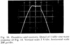
Hi Glen,
I forgot to mention that the thumbnail on post 107 refers to Cherry's amp (at 1kHz) and clipping of our amp (at 20kHz!!!) can be found here, last pic: http://home.tiscali.nl/audio/clipping.html
Cheers, Edmond.
Hi Glen,
I forgot to mention that the thumbnail on post 107 refers to Cherry's amp (at 1kHz) and clipping of our amp (at 20kHz!!!) can be found here, last pic: http://home.tiscali.nl/audio/clipping.html
Cheers, Edmond.
syn08 said:Well, those numbers are coming straight from the manufacturer's spec. I guess that's what an amp designer would take as input (vs. Stereophile measurements), isn't it? If you look at the Sonus Faber's 1.7ohm, then designing for 1ohm load is probably a little of an overkill but certainly not absurd. Otherwise, I'm pretty sure that the same market that allowed a pair of $40,000 speakers would certainly allow an amp designed to drive 1ohm, disregarding the cost
[snip]
Hi Ovidiu.
OK, 1.7 Ohm. This a very good example that we should simply ignore. I insist that this kind of practice is a bloody shame. For $40,000 these Italian guys could have paid a little bit more attention to the impedance characteristics, but apparently they don't bother. Besides, the frequency response is far from flat too. From my part, I'm reluctant to reckon with this ill designed piece of.....
Cheers, Edmond.
Ill designed speakers
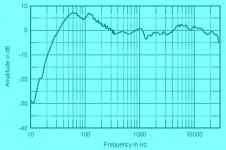
Hi Ovidiu,
In the mean time I had a closer at this allegedly high-end loud speaker. It peaks at around 60...120Hz by at least 6dB. No wonder that the impedance drops by an equal amount at these frequencies. No further comments (of course).
Cheers, Edmond.
Hi Ovidiu,
In the mean time I had a closer at this allegedly high-end loud speaker. It peaks at around 60...120Hz by at least 6dB. No wonder that the impedance drops by an equal amount at these frequencies. No further comments (of course).
Cheers, Edmond.
Attachments
syn08 said:
Well, those numbers are coming straight from the manufacturer's spec. I guess that's what an amp designer would take as input (vs. Stereophile measurements), isn't it? If you look at the Sonus Faber's 1.7ohm, then designing for 1ohm load is probably a little of an overkill but certainly not absurd. Otherwise, I'm pretty sure that the same market that allowed a pair of $40,000 speakers would certainly allow an amp designed to drive 1ohm, disregarding the cost
If our amp would be intended for a commercial product, I wouldn't specify the current implementation at 4ohm. I see the 4ohm (resistive load) good performance only as a guarantee for an overall 8ohm load (speaker reactive load) good performance. If you recall, most of the key performance are barely measurable at 8ohm resistive load, so then the spec could simply use the "better than" sintagm.
Could we in principle drive 1 ohm with our amp? Based on what I've seen so far I would say "no way". At over 3 amps peak per device, the OPS THD increases pretty quickly. At 5 amps per device (for a total of 15A) the EC OPS is almost 900ppm, so over an order of magnitude larger than at 3A. Of course, more devices could be paralelled but then to me this is not practical from both a technical and cost perspective. Verticals or bipolars are needed in such a case.
Based on the very few measurements I did on our EC OPS using Fairchild's FQA20N19 and FQA20P12 verticals (with all the bias and gate adjustments required) at Ibias=150mA, the open loop THD20 at 4ohm is around 150ppm while at 2ohm (Ipeak=6.6A/device) the THD20 is around 380ppm. Unfortunately I am not able to go under 2 ohm with the current load and heatsinks...
I think that the key thing to keep in mind here is that the amplifier should not clip or misbehave when briefly called upon to deliver a peak current that could correspond to a 1 ohm load. That is indeed a lofty goal, and need not always be realized.
Based on reactance and stored energy, it is in principle possible for a loudspeaker, when driven with the right waveform, to demand considerably more current than would be predicted by looking at its minimum impedance. This can, in principle be by a factor of two or more. It is probably rare, but should be kept in mind. This is a big part of the idea behind so-called high current amplifiers. Otala studied this and there is also information on this in my IIM paper at www.cordellaudio.com.
This is not to say that the amplifier even comes close to meeting its normal distortion specs during that brief burst. If you can handle a 2-cycle tone burst into one ohm without clipping or blowing up, you are pretty much there, in my opinion, even if the distortion would be a huge 0.1%. You do not want the amplifier to lose control of the speaker under these conditions.
For a 100-watt, 8-ohm amplifier, this might translate to a 40-amp peak output current capability. With three output pairs, this would mean about 13 Amps per device. You may not be far from being able to do that briefly with those devices if you have enough gate drive. That is certainly possible with the verticals I am familiar with, but I must admit that I usually shut them down at about 10A per device for anything other than a very short duration event.
Cheers,
Bob
Bob Cordell said:
For a 100-watt, 8-ohm amplifier, this might translate to a 40-amp peak output current capability. With three output pairs, this would mean about 13 Amps per device. You may not be far from being able to do that briefly with those devices if you have enough gate drive. That is certainly possible with the verticals I am familiar with, but I must admit that I usually shut them down at about 10A per device for anything other than a very short duration event.
Bob,
While I agree with you that an 8ohm amp should survive 1ohm load chirps, unfortunately the laterals won't make it to 13 amps, not even at the max Vgs of 15V. Though, I'm pretty sure they won't blow (they have Idmax=7A). I have no idea how the chirp distortions could be measured. If you have any information about, I would be happy to give it a try (the spectrum analyzer has chirp output features) and push the amp as much as possible.
To safely deliver 40A of chirp current, my estimate is a minimum of 5 lateral devices, or a total of 10 per channel. As I've already mentioned, this is not practical (matching starts to be an issue) and neither economical (laterals are about twice the price of Fairchild verticals).
Could you provide a link for your protection schematic? Thanks!
Congratulation on creating this great beast. Way beyond my level of comprehension of electronics but very cool to see implemented by people that know their stuff.
It definitely picks my curiosity in terms of the kind of sound it produces.
I would have been even better if boards were available to make construction a little more accessible.
A question about the output stage, seems to me that paralleling a sufficient amounts of good japanese high power bipolars would have done the trick for any reasonable operation conditions, that is if the amp is stable on reactive loads to begin with. Is the true? Maybe I am not familiar enough with this design.
I often wondered, but never measured, what kind of currents can be achieved by pulsing a few ms into a short before the intrinsic reactance of the PS limits the spike. Has anyone here tried? Is a figure like 50 amp really realistic?
- Status
- This old topic is closed. If you want to reopen this topic, contact a moderator using the "Report Post" button.
- Home
- Amplifiers
- Solid State
- PGP (Pretty Good Poweramp)