Re: Re: Re: Re: Re: Re: Your amplifier
I second that. I've used Amber analyzer for all developement I've done at Creek Audio (I don't remember the exact model number), and I would love to get one for my home lab.
Cheers
Alex
Originally posted by syn08 The Amber analyzers were among the best in the 80's. They are built with standard parts, so they are very easy to mantain and repair. Even today the performance delivered by these instruments is amazing, AP has certainly learned a lot from these guys! I would heartly recommend getting one, if the budget is limited.[/B]
I second that. I've used Amber analyzer for all developement I've done at Creek Audio (I don't remember the exact model number), and I would love to get one for my home lab.
Cheers
Alex
Re: Re: Re: Re: Re: Your amplifier
Thanks Bob, good suggestion. We should add some measurements on the amp noise. Actually it seems to me that the amp output is a little less noisier than the back-to-back and that is probably because of the amp BW. But indeed our amp noise performance is probably pretty good, for sure the low noise 2SA970/2SC2240 trannies helped a lot.
Bob Cordell said:
Thanks! Keep up the good work.
BTW, the noise of your amplifier must be pretty low to have gotten that earlier THD-20 picture with little more fuzz than the back-to-back in the 80 kHz bandwidth. Have you tried to calculate your amplifier's input-referred noise in nV/rt Hz?
Cheers,
Bob
Thanks Bob, good suggestion. We should add some measurements on the amp noise. Actually it seems to me that the amp output is a little less noisier than the back-to-back and that is probably because of the amp BW. But indeed our amp noise performance is probably pretty good, for sure the low noise 2SA970/2SC2240 trannies helped a lot.
bigwill said:this amplifier is ridiculous
Thank you for sharing your opinion. It is really helpful!
Re: Re: Re: Re: Re: Re: Re: Your amplifier
Some ask top dollar:
http://www.torontosurplus.com/redirect.php?middleframe=http://www.torontosurplus.com/tes/tes09.htm
but you can get it also for one quarter of that (no IMD option I think), this one is a steal:
http://www.users.qwest.net/~jbau/tstequip.htm
Jan Didden
x-pro said:
I second that. I've used Amber analyzer for all developement I've done at Creek Audio (I don't remember the exact model number), and I would love to get one for my home lab.
Cheers
Alex
Some ask top dollar:
http://www.torontosurplus.com/redirect.php?middleframe=http://www.torontosurplus.com/tes/tes09.htm
but you can get it also for one quarter of that (no IMD option I think), this one is a steal:
http://www.users.qwest.net/~jbau/tstequip.htm
Jan Didden
Re: Re: Re: Your amplifier
Hi Bob,
First, thank you for your kind and thoughtful comments.
Regarding bootstrapping, it is not the VAS that is bootstrapped, rather the +/-24V power supply of the input stage that is tracking the input voltage. Please have a look at the schematics: http://home.tiscali.nl/audio/FrontEndSch.html and: http://home.tiscali.nl/audio/MPSUSch.html
In doing so the Early effect (which is hard to simulate btw) has no chance at all to spoil the amp, as all Vce's of the trannies in the input stage are held at a constant level. Don't worry about HF instabilities, as this kind of bootstrapping is quite harmless. To be on the safe side, we shunted HF signals by means of C35 (390pF).
Also the NDFL stage is bootstrapped, this time by means of simple resistive dividers (R32,33,37,38).
Regarding the electrolytic cap, we still have the option to add a servo and put this one on the PCB of the differential to single ended line receiver (one of our next projects). Whether it's really necessary depends on distortion measurements at very low frequencies, which will be done ASAP.
>Of course, some people mistakenly think that a shunt capacitor in the feedback path is not in the signal path") .
.
Please Bob, do you really think I'm that stupid?
Regarding amp A and B, I'm guessing that everybody would choose A, because in most cases there is no need to use a coil at all and they can simply bypass or remove that evil thing. Remember that the wiring from amp to speaker also represents a inductance of the same order, but funny enough some people (actually only two, no names) can only hear the presence of a inductance when it sits inside the amp, not outside or in a loud speaker
Cheers, Edmond.
Bob Cordell said:Hi Edmond, you are most welcome for the appreciative words, and your effort here is very deserving of it.
I must admit, I was confused enough about the bootstrapping that it was not a typo, but it was also not backed up by a lot of thought. Is it the VAS that is bootstrapped to the output signal?
Two things usually cause me to exercise caution when bootstrapping. I do use it, by the way, in some cases. The first thing that worries me is the possible appearance of some unwanted feedback, maybe even positive, at high frequencies. The second is that the circuit may behave in unanticipated ways under clipping or fault conditions.
Regarding the d.c. servo, I always seem to have +/- 15 V lying around, so that is not a problem. Audio-grade op amps should be used in servo circuits, but it is a misconception that when properly used in a servo circuit they need to be as good as the signal path. In a poorly designed servo, where the output of the op amp was only minimally attenuated before being applied to the amplifier input, one would have to have an exceptionally good one. If, on the other hand, its output is attenuated by 100:1 or even 1000:1, depending on amount of correction needed, it need not be as good (i.e., not garbage, but good audio grade, at least as good as an OPA604, for example).
Although there are some pretty good electrolytics out there, there is enough anecdotal information on capacitors so as to avoid electrolytics. The dc servo integrating capacitor should be decent, such as a polypropylene or better. My view is that if you believe that capacitors in the signal path can make a difference, then you virtually never put an electrolytic in the signal path. Of course, some people mistakenly think that a shunt capacitor in the feedback path is not in the signal path
I think the coil discussion was not without value. I'm not sure to what extent I buy into the coil thing either, but I do like to be on the safe side. To me, the safe side means two things: 1) there is a coil if it is necessary to make the design unconditionally stable; 2) the coil is as small as possible.
This, in my view, is not that much different than believing that 0.0001% is audibly superior to 0.001% distortion. There is a little bit of faith and belief system in each.
Here's another way of looking at it. Lets say we offered the community here their choice of two different amplifiers. Amplifier A has 0.0001% THD-20 and uses a 2.5 uH output coil. Amplifier B has 0.001% THD-20 and uses only a 0.5 uH output coil. I'm guessing that some would choose A and some would choose B.
In any case, the sweat and intellect that you have put into this amplifier has stimulated much very worthwhile discussion.
Cheers,
Bob
Hi Bob,
First, thank you for your kind and thoughtful comments.
Regarding bootstrapping, it is not the VAS that is bootstrapped, rather the +/-24V power supply of the input stage that is tracking the input voltage. Please have a look at the schematics: http://home.tiscali.nl/audio/FrontEndSch.html and: http://home.tiscali.nl/audio/MPSUSch.html
In doing so the Early effect (which is hard to simulate btw) has no chance at all to spoil the amp, as all Vce's of the trannies in the input stage are held at a constant level. Don't worry about HF instabilities, as this kind of bootstrapping is quite harmless. To be on the safe side, we shunted HF signals by means of C35 (390pF).
Also the NDFL stage is bootstrapped, this time by means of simple resistive dividers (R32,33,37,38).
Regarding the electrolytic cap, we still have the option to add a servo and put this one on the PCB of the differential to single ended line receiver (one of our next projects). Whether it's really necessary depends on distortion measurements at very low frequencies, which will be done ASAP.
>Of course, some people mistakenly think that a shunt capacitor in the feedback path is not in the signal path
.Please Bob, do you really think I'm that stupid?
Regarding amp A and B, I'm guessing that everybody would choose A, because in most cases there is no need to use a coil at all and they can simply bypass or remove that evil thing. Remember that the wiring from amp to speaker also represents a inductance of the same order, but funny enough some people (actually only two, no names) can only hear the presence of a inductance when it sits inside the amp, not outside or in a loud speaker
Cheers, Edmond.
Is your crystal receiver finally working?bigwill said:this amplifier is ridiculous
Re: Re: Re: Re: Re: Re: Re: Re: Your amplifier
Hi Jan,
thanks for the links. Now I can say the Amber model number I've used - it is 3501. I am really tempted to get that one...
Cheers
Alex
janneman said:Some ask top dollar:
Hi Jan,
thanks for the links. Now I can say the Amber model number I've used - it is 3501. I am really tempted to get that one...
Cheers
Alex
Re: Re: Re: Re: Re: Re: Re: Re: Re: Your amplifier
Alex,
Don't rush, watch EBay. I got my Amber 5500 for $400 (guaranteed as working). Last week another 5500 (seemingly in good condition) was sold for $200. The 3501 sells for about the same price, but the 5500 is a much better, fully digital, instrument. If you though decide for a 3501 (granted, is smaller and lighter that the 5500 50lb monster) careful to have the power supply included. 3501 needs an external 13VAC power supply.
Originally posted by x-pro
thanks for the links. Now I can say the Amber model number I've used - it is 3501. I am really tempted to get that one...
Alex,
Don't rush, watch EBay. I got my Amber 5500 for $400 (guaranteed as working). Last week another 5500 (seemingly in good condition) was sold for $200. The 3501 sells for about the same price, but the 5500 is a much better, fully digital, instrument. If you though decide for a 3501 (granted, is smaller and lighter that the 5500 50lb monster) careful to have the power supply included. 3501 needs an external 13VAC power supply.
Re: Re: Re: Re: Re: Re: Re: Re: Re: Re: Your amplifier
Thanks for the advice. 3501 would be more than enough for my needs and I am very familiar with it .
Cheers
Alex
syn08 said:Don't rush, watch EBay. I got my Amber 5500 for $400 (guaranteed as working). Last week another 5500 (seemingly in good condition) was sold for $200. The 3501 sells for about the same price, but the 5500 is a much better, fully digital, instrument. If you though decide for a 3501 (granted, is smaller and lighter that the 5500 50lb monster) careful to have the power supply included. 3501 needs an external 13VAC power supply.
Thanks for the advice. 3501 would be more than enough for my needs and I am very familiar with it
.Cheers
Alex
traderbam said:I must be in competent. I have done what you asked and am still no wiser, except for a power figure which I said was 400W rather than 200W.
PGP:
output stage THD20 -82dB (Ovidiu's measurement)
overall THD -120dB (Ovidiu's measurement)
=> main loop NFB of 38dB at 20kHz.
Measured at 200W avg into 4 ohms resistive
BC:
output stage THD20 -64dB (Bob's measurement)
overall THD -104dB (Bob's measurement)
=> main loop NFB of 40dB at 20kHz.
Measured at 50W avg into 8 ohms resistive
Which of these numbers is totally wrong?
Also, have you got the stability difference between the PGP and the BC amp? I believe you have simulated both circuits.
Thx.
Hi Brian,
Both are wrong. Main loop NFB at 20kHz != overall THD20 - output stage THD20.
Maybe this enlightens you: at 20kHz the 2nd harmonic = 40kHz, 3rd harmonic = 60kHz, etc.
As for stability differences, yes, I have simulated both circuits.
Cheers, Edmond.
Ok, I see. You are assuming a 6dB/oct feedback roll-off. Ok. You haven't said what the vlaues of H2, H3, etc are. Nevermind. Can you tell me what the actual main fb loop gain is at 20kHz with a 4 ohm load?Hi Brian,
Both are wrong. Main loop NFB at 20kHz != overall THD20 - output stage THD20.
Maybe this enlightens you: at 20kHz the 2nd harmonic = 40kHz, 3rd harmonic = 60kHz, etc.
As for stability differences, yes, I have simulated both circuits.
Cheers, Edmond.
I can estimate the stability margin from your published pulse response.
Brian
Thanks Edmond.
I think that the reason your version initially had a fighting VAS issue is because you tried to lighten the load on the current mirrors too much.
That's why I stuck with 1k loads for the 12W (not-so-serious) amp. Because of this, the 12W amp doesn't have a fighting VAS issue at all. Although this has attracted some criticism, when using BJT LTP's a 1k load really isn't that bad (With JFETs for the LTP's it would be an entirely different story).
Due to the high transconductance of SS BJTs, enough LTP gain can still be had (which is double with the I mirrors) and the linearity is still excellent - and lightening the load even by 10 times really does surprisingly little for the amplifiers overall THD performance; the majority of the distortion comes from the VAS and the OPS, and this is where I am concentrating my efforts in my next version of the design - the 300W monster.
Incidentally though, I am using lighter loads this time for close to 40dB gain in each LTP, but I am also using dual MATXX trannies for the LTP's and SMD high ft/low Cob I-mirror configured dual pairs for the current mirrors and resistors matched for 0.1%.
Good luck with the RET OPS. Let us know how it goes.
Cheers,
Glen
Glen, can you point me to that thread - I treid searching but could not locate it.
thanks
Hey Edmond.
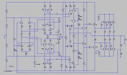
Sorry if a bit off topic, but you can tell me off if so. Here is a preview of the schematic that I promised to send you of my 300W TMC EC amp (based on the 12W one).
LTP loads are 3k, fancy duals used for the LTP’s and I mirrors and 0.1% matched resistors for accurately defined currents, thus no VAS fighting problems. Close to 40dB gain per LTP.
This is a simplified schematic for initial simulation purposes – no EC yet and only 3 output pairs biased at 3A for 150W class A into 8 ohms (final circuit will have 20 pairs and 6.25A bias).
I also haven’t included the clipping VAS voltage swing / current limiting clamps yet.
Still a crude OPS and I have only used ordinary bjts for most of the small signal trannies and I haven’t added the EC to the output stage yet, but the circuit is simulating 5ppm THD-20 at 150W rms into 8 ohms.
I've added a dual Jfet buffer (U404) to the front end, so no need for big caps or a servo. Offset null trimpot will be put in the emitters of the bjt CCS pair biasing the jfets.
Cheers,
Glen
Attachments
Bonsai said:Glen, can you point me to that thread - I treid searching but could not locate it.
There are maybe a dozen posts in the BJT Vs MOSFET thread.
Cheers,
Glen
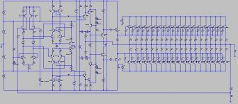
OK, here is the MKII sim version. The jfet input buffer was adding a ppm or so to the closed loop THD, so I fixed that by using a MAT03 PNP dual to make a pair of CFP's with the U404. The MAT03 is a nice low noise device with high Cob, which effectively miller compensates each CFP and makes them unconditionally stable.
Still no EC and the TMC is a bit over-compensated at fT=~1MHz, but have added the rest of the 20 output pairs and cranked the bias up to 6.25A.
THD-20 at 300W RMS into 4 ohms sims 5.38ppm
Cheers,
Glen
Still no EC and the TMC is a bit over-compensated at fT=~1MHz, but have added the rest of the 20 output pairs and cranked the bias up to 6.25A.
THD-20 at 300W RMS into 4 ohms sims 5.38ppm
Cheers,
Glen
Attachments
G.Kleinschmidt said:Thanks Edmond.
I think that the reason your version initially had a fighting VAS issue is because you tried to lighten the load on the current mirrors too much.
That's why I stuck with 1k loads for the 12W (not-so-serious) amp. Because of this, the 12W amp doesn't have a fighting VAS issue at all. Although this has attracted some criticism, when using BJT LTP's a 1k load really isn't that bad (With JFETs for the LTP's it would be an entirely different story).
Due to the high transconductance of SS BJTs, enough LTP gain can still be had (which is double with the I mirrors) and the linearity is still excellent - and lightening the load even by 10 times really does surprisingly little for the amplifiers overall THD performance; the majority of the distortion comes from the VAS and the OPS, and this is where I am concentrating my efforts in my next version of the design - the 300W monster.
Incidentally though, I am using lighter loads this time for close to 40dB gain in each LTP, but I am also using dual MATXX trannies for the LTP's and SMD high ft/low Cob I-mirror configured dual pairs for the current mirrors and resistors matched for 0.1%.
Good luck with the RET OPS. Let us know how it goes.
Cheers,
Glen
Hi Glen,
It seems that there is some confusion about the "fighting VAS' issue. Actually, there are two issues:
1. Stability of the DC operating point (that is what you are referring to, right?)
2. AC common mode currents at higher frequencies, that is what I am referring to.
So I'm afraid we are on cross purposes.
Let me explain why the latter forms a potential problem. As the Miller caps provide local NFB (the higher the frequency, the more FB), the output impedance of each VAS gets quite low at higher frequencies. IOW, the outputs behave more or less as a voltage source.
The output level of each VAS depends on many factors, like the open loop gain of the input stage, gain of the VAS and of course the value of the Miller caps. So, much chance that the individual output levels are not exactly equal, that is, when the outputs are not tied together of course.
As everybody knows, paralleling different voltage sources mean trouble, also in this case. As a result, high common mode currents will circulate, which compromise the performance.
BTW, this is the reason why Bob and his buddy Brian shy fully complementary topologies.
Though adding to complexity, a common mode control loop (CMCL) solves both issues at once and the open loop gain of the VAS is much higher. For example, if I loaded the VAS inputs in our front end with 1k, the distortion of the front end gets 12 times higher and the distortion of the complete amp more than doubles.
I have to leave now, but later on I've a look at your design.
Cheers, Edmond.
Edmond Stuart said:
Hi Glen,
It seems that there is some confusion about the "fighting VAS' issue. Actually, there are two issues:
1. Stability of the DC operating point (that is what you are referring to, right?)
2. AC common mode currents at higher frequencies, that is what I am referring to.
OK. The term has be use to describe both things here, and you did actually mention #1, I thought.
Edmond Stuart said:The output level of each VAS depends on many factors, like the open loop gain of the input stage, gain of the VAS and of course the value of the Miller caps. So, much chance that the individual output levels are not exactly equal, that is, when the outputs are not tied together of course.
As everybody knows, paralleling different voltage sources mean trouble, also in this case. As a result, high common mode currents will circulate, which compromise the performance.
BTW, this is the reason why Bob and his buddy Brian shy fully complementary topologies.
I really don't see this as as having to be much of a problem at all. In my design the LTP gains are rather accurately defined/matched by the emitter degeneration and the resistive loads which also serve the purpose of biasing the VAS buffer emitter followers. The VAS gains are accurately matched by virtue of the 100R emitter degeneration resistors and each VAS sees an identical collector load as the collectors are essentially connected together anyway – no gain tracking problems there.
The miller compensation capacitors corner with the resistive load, so the HF roll off of each VAS is accurately defined. So long as the miller compensation caps are matched to 1% or so the HF roll off of each VAS will track quite nicely too.
Not sure that the circulating currents due to gain missmatch will be very high either. A miller compensated VAS can have a very low output impedance at 1MHz and look quite like a voltage source, but what is it at 20kHz? Several k in my design.
Edmond Stuart said:
I have to leave now, but later on I've a look at your design.
Whadda ya think of my CPF Jfet input buffer? for symetrical BJT LTP inputs?
Consider the merits:
1) Very Low THD
2) Low noise
3) No input resistor bootstrapping required for high input impedance, so no funny LF behaviour.
4) No capacitors (inc big electrolytics) required.
5) No servo required.
6) High Zin
Cheers,
Glen
Re: Re: Re: Re: Your amplifier
Hi Edmond,
Thanks for these answers. I will indeed have to spend more time looking at the schematic.
Regarding the matter of the shunt capacitor in the feeback path, that comment was in no way directed at you. When I take the time to raise issues on this forum, I am usually trying to adrress in an educational way all of the readers. What I said is, unfortunately a true statement, but it was not directed at you.
While I agree that in many cases people can get away without a coil on amplifiers that are designed to use one, it is likely not a wise idea. I would not be the least surprized if there are amplifiers out there without coils that experience an occasional spurious oscillation, maybe on a signal peak or edge, that influences the sound. It is also not always the case that a large capacitance is the worst case for such amplifiers. I would never, ever ship an amplifier that could not tolerate at least 100pF to 0.01 uF right across its terminals (bare, bare, minimum criteria, and not what I refer to as unconditionally stable). Anyway, I don't want to rekindle that coil discussion, so we may just have to agree to disagree on this one.
Cheers,
Bob
Edmond Stuart said:
Regarding the electrolytic cap, we still have the option to add a servo and put this one on the PCB of the differential to single ended line receiver (one of our next projects). Whether it's really necessary depends on distortion measurements at very low frequencies, which will be done ASAP.
>Of course, some people mistakenly think that a shunt capacitor in the feedback path is not in the signal path
Please Bob, do you really think I'm that stupid?
Regarding amp A and B, I'm guessing that everybody would choose A, because in most cases there is no need to use a coil at all and they can simply bypass or remove that evil thing. Remember that the wiring from amp to speaker also represents a inductance of the same order, but funny enough some people (actually only two, no names) can only hear the presence of a inductance when it sits inside the amp, not outside or in a loud speaker
Cheers, Edmond.
Hi Edmond,
Thanks for these answers. I will indeed have to spend more time looking at the schematic.
Regarding the matter of the shunt capacitor in the feeback path, that comment was in no way directed at you. When I take the time to raise issues on this forum, I am usually trying to adrress in an educational way all of the readers. What I said is, unfortunately a true statement, but it was not directed at you.
While I agree that in many cases people can get away without a coil on amplifiers that are designed to use one, it is likely not a wise idea. I would not be the least surprized if there are amplifiers out there without coils that experience an occasional spurious oscillation, maybe on a signal peak or edge, that influences the sound. It is also not always the case that a large capacitance is the worst case for such amplifiers. I would never, ever ship an amplifier that could not tolerate at least 100pF to 0.01 uF right across its terminals (bare, bare, minimum criteria, and not what I refer to as unconditionally stable). Anyway, I don't want to rekindle that coil discussion, so we may just have to agree to disagree on this one.
Cheers,
Bob
- Status
- This old topic is closed. If you want to reopen this topic, contact a moderator using the "Report Post" button.
- Home
- Amplifiers
- Solid State
- PGP (Pretty Good Poweramp)