Efragnani, those sinks between TO-92 parts.... I think they simply get things more difficult, since the goal is to thermocouple both devices, not to sink the heat they might produce. That's my 2 cents.
SmartX21, i agree with you and i'll discart them soon.
") Thanks.
Thanks.I used thermal paste and heatshrink tubing. Still the 550 ran hotter than the 560. It was noticeable when feeling with my finger. I haven't tried the glue as I wasn't sure if one would need replacing. I only had a few left so I bought some off ebay. The HFE is a lot lower than the ones I have from Mouser so they may be fake. Not going to use them here.
I have something wrong again now after shorting that transistor. I will have to pull all the devices and test the voltages. Should be the same side to side since this board is so symmetrical. Hopefully I will find the problem. I hope it is not the outputs since I don't have any more of those. I'll report back after I have had a chance to work on it some more.
I have something wrong again now after shorting that transistor. I will have to pull all the devices and test the voltages. Should be the same side to side since this board is so symmetrical. Hopefully I will find the problem. I hope it is not the outputs since I don't have any more of those. I'll report back after I have had a chance to work on it some more.
Have you seen some of Lazy Cat's latest posts on those resistors and diodes? Reposted here for discussion, because most of the VSSA thread is dealing with other issues now:...got burn 4 pcs 10 ohm resistor because of that transistor...
The "pulsed current" reference is in regard to the resistors failing with the abrupt turn-on of the SMPS LC has recommended, so that does not apply to most people here.R19, R20 are in recomendation to be replaced with pulsed current ones. But according to the last shootout test I would recommend to shorten serial diode D5, D6 and resistor R19, R20 with short wire. There is an improvement noticed in bass region if serial R-D is shortened...
The other part is more interesting. Also Shaan has changed the diode recommendation after some listening (at higher voltage I believe):
I tested without the diode for a while, but decided to leave it in out of caution.1N4148, so far.Originally Posted by gives you wing: hey, Shaan
which is the best for the sound result as your experiment before, the diode in V+/- rail, 1N4148 / Schotky / MUR?
thanks, g.y.w.
Couldn't source MUR. Local stockist out of stock.
Will update once the experiments are done.
LC also posted this:
This is basically what I noticed earlier, and what led me toward using the Cap Multiplier power supply. Using an oscilloscope, you can see some evidence of rectifier ripple at the output. Not much, but there is a chance you could hear that depending on other conditions, especially if one uses a fairly lightly filtered supply.Each resistor-diode pair shorten with one wire. By listening tests was confirmed more grip and better bass and even more resolution in mid-high region.
The 100 Hz ripple noticable at the output was the same as before (barely noticable), since we use CCS for the input stage.

Efragnani, those sinks between TO-92 parts.... I think they simply get things more difficult, since the goal is to thermocouple both devices, not to sink the heat they might produce. That's my 2 cents.
Its a way to add thermal mass, not necessarily sink the heat. It slows the thermal time constant.
@PMI,
So no 10 ohm resistor's & no MUR's diode?
I can try it next time ...
I'm thinking to reduce 10 ohm resistor to smaller value, cause I don't have 0.5 or 1 watt.
I use only 13600uF per rail for stereo, and a big 35 A bridge diode.
I need to hear it in the silence night
at day can't hear any ripple (turn it on from 10 am till 9 pm)
I have a noisy environment here, many fans, computer, freezer etc
Depends on other conditions, and on what other people say. That is why I offer this for discussion.@PMI,
So no 10 ohm resistor's & no MUR's diode?
( I am not exactly known for being the fastest to implement changes...
)The 10R might have saved some transistors for some people, when it turns into a fuse. For others it may just be an annoyance when it fails. In normal use, and with a strong power supply, the diode is always forward biased. With a weaker supply (small filter caps or small transformer), the diode might have some benefits it it helps keep the supply voltage stable at the front end.
( I am not exactly known for being the fastest to implement changes...
I think I have implemented it a year ago: R-D String
There you go, myI think I have implemented it a year ago: R-D String
 point exactly (chuckle) Someone has been over this ground before.
As I see it, the main reason for the diode would be to hold up the front end supply while the main supply rails are pulled down by demand from the output stage. I believe someone called it a "poor-man's dual rail supply".
If this does not happen in normal use, or if the DC supply is highly filtered and the sag is not evident in the audio spectrum, one may be able to dispense with the diode.
That leaves a 10R between two 1000 uFd capacitors. Basically a PI filter. I would not be as willing to dispense with that, but as I said, it depends on the conditions. In cases where the rails have a lot of ripple, it may be cheap insurance.
That leaves a 10R between two 1000 uFd capacitors. Basically a PI filter. I would not be as willing to dispense with that, but as I said, it depends on the conditions. In cases where the rails have a lot of ripple, it may be cheap insurance.
It could be depending on conditions, but every time I compare CRC with straight C I always like the straight C by a huge margin (I think it is the supply impedance that is important). Its like medicine.
Now I can see that it can become a PI filter...
That is outstanding, how do you measure that?My VSSA is stable without compensation. I used 2SA1209/2SC2911 for VAS. With input open, residual noise is below 5mVpp at about 100kHz. And I can not hear anything from speaker ever my ear almost touch the speaker.
At home I can only measure noise signals down to about 10 millivolts using a standalone 100 MHz BW oscilloscope, and that is on one of my good days...
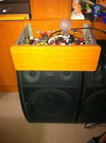
My PeeCeeBee
My build sitting on an unfinished home-made case.
I am always guaranteed of good music that comes out of it while waiting for my other case parts.
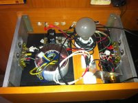
Here is my novice experience during the build:
1. I ensured the two 2.2k FB resistors were closely matched.
2. I ensured the two 100R FB resistors were closely matched.
3. Since I didn't have instrument or jig to match hFEs of BC5xx/BC4xx, I just measured the base-emitter resistance, and base-collector resistance, and ensured that they closely matched. My point was since matched transistors were hard/difficult to find anyway, and some parts in the circuit contained unmatched parts in a certain way, I thought I could live with this situation without imposing hard-rule strictness to the match hFEs requirement. Being close to a match was acceptable I think, and I reasoned also that hFE profile was in anyway not guaranteed to be the same during operation even if it was pre-matched and one would tend to be hotter than the other, etc.
For above, I am a newbie so forgive me of this little ignorance.
4. First channel, I put compensation caps of 24pF since I observed that the output DC reading was not steady. When it became steady, DC offset can be read but needs to be lowered. Putting a parallel resistor of high value (from 150k to 2 MegaOhms) can balance this DC offset. It can be done by clipping an alligator clips at both ends of the 15k resistor, and connecting the other ends of the alligator clips with the trial resistor. In my case, I found 330k resistor was appropriate with the DC offset reading down to 2mV. Contented with the value, I soldered it on the board.
5. Second channel, DC reading was steady so no need compensation caps. DC offset was 150mV, and I found 1.9 MegaOhms resistor which lower the DC offset down to 5mV. Contented with the value, I soldered it on the board.
By the way, in this channel I used BC547B / BC556B while the first channel was BC546B / BC556B. Listening-wise comparison, the two channel is no different than the other.
Best regards.
My build sitting on an unfinished home-made case.
I am always guaranteed of good music that comes out of it while waiting for my other case parts.
Here is my novice experience during the build:
1. I ensured the two 2.2k FB resistors were closely matched.
2. I ensured the two 100R FB resistors were closely matched.
3. Since I didn't have instrument or jig to match hFEs of BC5xx/BC4xx, I just measured the base-emitter resistance, and base-collector resistance, and ensured that they closely matched. My point was since matched transistors were hard/difficult to find anyway, and some parts in the circuit contained unmatched parts in a certain way, I thought I could live with this situation without imposing hard-rule strictness to the match hFEs requirement. Being close to a match was acceptable I think, and I reasoned also that hFE profile was in anyway not guaranteed to be the same during operation even if it was pre-matched and one would tend to be hotter than the other, etc.
For above, I am a newbie so forgive me of this little ignorance.
4. First channel, I put compensation caps of 24pF since I observed that the output DC reading was not steady. When it became steady, DC offset can be read but needs to be lowered. Putting a parallel resistor of high value (from 150k to 2 MegaOhms) can balance this DC offset. It can be done by clipping an alligator clips at both ends of the 15k resistor, and connecting the other ends of the alligator clips with the trial resistor. In my case, I found 330k resistor was appropriate with the DC offset reading down to 2mV. Contented with the value, I soldered it on the board.
5. Second channel, DC reading was steady so no need compensation caps. DC offset was 150mV, and I found 1.9 MegaOhms resistor which lower the DC offset down to 5mV. Contented with the value, I soldered it on the board.
By the way, in this channel I used BC547B / BC556B while the first channel was BC546B / BC556B. Listening-wise comparison, the two channel is no different than the other.
Best regards.
Attachments
.....We are in the fight to solve the problems and doing tests....
Efragnani, those sinks between TO-92 parts.... I think they simply get things more difficult, since the goal is to thermocouple both devices, not to sink the heat they might produce. That's my 2 cents.
See post #1111 by shaan where he debugged that metal used in combination with input pair needs a signal grounding wire for not causing amp specs to fluctuate. It did even make compensation caps unnessasary as i understood in that particular setup by member jaagut post #1095.Its a way to add thermal mass, not necessarily sink the heat. It slows the thermal time constant.
Last edited:
Hi Jason,
I did but those TO-3 MOSFET's are unobtanium these days. To bad because I have a few really nice TO-3 heatsinks. I have a drawer full of TO-3 BJT's but no amp for them that piques my interest. I'm sorry I haven't answered you. I was trying to find outputs for it but they cost more than all the other part put together and then youdon't know if you are getting the genuine article. I really, really appreciate the offer.
Blessings, Terry
Hi Guys,
This has probably been asked, but I have to ask why we continue to design amps that need devices that aren't made anymore. Aren't there devices being made that will work for this type of amp? I love the idea of the amp but there must be some way to make obtainable parts work for it.
Thanks, Terry
This has probably been asked, but I have to ask why we continue to design amps that need devices that aren't made anymore. Aren't there devices being made that will work for this type of amp? I love the idea of the amp but there must be some way to make obtainable parts work for it.
Thanks, Terry
Exicon TO3 lateral (both single and double die) Mosfets are available from Profusion plc in England, and are even better than original Hitachi lateral mosfets but also expensive.Hi Jason,
I did but those TO-3 MOSFET's are unobtanium these days. To bad because I have a few really nice TO-3 heatsinks. I have a drawer full of TO-3 BJT's but no amp for them that piques my interest. I'm sorry I haven't answered you. I was trying to find outputs for it but they cost more than all the other part put together and then youdon't know if you are getting the genuine article. I really, really appreciate the offer.
Blessings, Terry
Hi Jason,
I did but those TO-3 MOSFET's are unobtanium these days. To bad because I have a few really nice TO-3 heatsinks. I have a drawer full of TO-3 BJT's but no amp for them that piques my interest. I'm sorry I haven't answered you. I was trying to find outputs for it but they cost more than all the other part put together and then youdon't know if you are getting the genuine article. I really, really appreciate the offer.
Blessings, Terry
Newark has cut prices for BUZ901 and BUZ906 from $14 to $7.75.
BUZ901 - SEMELAB - N CHANNEL MOSFET, 200V, 8A, TO | Newark
- Home
- Amplifiers
- Solid State
- PeeCeeBee