Output inductor may also be needed for unconditional stability if one intends to torture (any) amp with high capacitance loudspeaker cables like Kimber, Goertz, etc. I remember many years ago when my friend had Audiolab 8000 integrated amp. That amp was without output inductor and only thing needed to trigger protection circuit was two 2,5m long Kimber 4TC cables per stereo channel (biwire). Amp oscillated without output inductor. Output inductor gives amp immunity towards capacitive loads but also changes the sound of (any) amp giving it a pinch of sharpness (accentuating harmonics). That's why John Curl does not suggest using it.
@Jason: Speaking of RF and high frequency in general...
Although the circuit is remarkably stable and well behaved, it can oscillate under some conditions. I observed this during testing last time, when it looked like I picked up some RF when I left a long open (unconnected and unterminated) input lead. It may have led to frying the output and VAS transistors on one rail (while I was admiring the waveform on my scope)
So I am wondering if the input filter should be set intentionally lower than it is now. Having a 1 megaherz bandwidth is impressive on one hand, but may not be good for safety on the other.
I was thinking that very thing about the input filter corner frequency. It is set quite high, but I simply followed the LC / Shaan recipe. A more realistic value might be 200kHz or so. Also, I didn't put the zobel option on board but it is a simple matter to add it at the speaker terminals inside the case if desired.
The pick up of RF or other noise was one of my motivations for putting the 100k at the input, to prevent the input floating at a very high impedance.
As for values the almost universal values of 10R-0.1uF are fine, as PMI has already suggested. If an inductor is going to be used, 4R7||1-2uH should be fine (0.5" diameter and 12 to 16 turns). The zobel is placed 'closest' to the amplifier and the inductor towards the speaker, just anyone not sure doesn't know this already.
Hi guys,
I follow quietly this thread for some time and I'd like to give some information about the Zobel and output inductor.
In my opinion, if you are using lateral FETs you don't need the Zobel nor the inductor. I have played recently with Lat. FETs and for some reason I find that they have some intrinsic output inductance. I use them in standard push-pull source follower configuration, the same that you have in Shaan circuit. They run at 150-200 mA and I have tested them in different amplifiers as a replacement of BJT transistors - always the same findings.
If you test with square wave at some high frequency, for example 50kHz, you'll notice that with Zobel there is slight ringing on the rising edges. Depending on the Zobel capacitor and the ringing frequency I calculated output inductance of about 0.7uH. Have in mind that I measure at the board outputs - no cable is in the way, only short circuit path.
When the Zobel is removed the square wave is very clean when the output is tested with pure resistive load. If you use resistor//capacitor as a load, the ringing is back depending on the capacitor value.
In short, I think you are safe without Zobel or with very light one (say 10 ohms, 33nF) and without inductor because you already have one of 0.7uH at the output.
Hope that this helps.
Regards
I've tried so far BUZ901/BUZ906 and ALF08N16/ALF08P16.
I have no explanation, and if I hadn't seen it with my own eyes on the scope, it would have been hard for me to believe it. At first I thought it's circuit specific, but after I confirmed in another two amps I just take it as a fact of life
I think it's useful for DIY-ers to have it in mind in their projects and it would be very nice if someone else could also confirm it.
Hitachi LatFET application circuits have both Zobel and output inductor but it could be that it is part of standard circuit design practice to include all stability features in amps to be safe. I am really surprised because Hitachi application notes state that LatFets are prone to oscillations.
Ringing with output inductor is not unusual and is reported in JLH Mosfet amplifier. Most probably it is because it makes some kind of resonant circuit with loudspeaker cable, not necessarily because the amp itself is unstable, but than again you measured at pcb terminals. I am indeed very surprised!
Ringing with output inductor is not unusual and is reported in JLH Mosfet amplifier. Most probably it is because it makes some kind of resonant circuit with loudspeaker cable, not necessarily because the amp itself is unstable, but than again you measured at pcb terminals. I am indeed very surprised!
Last edited:
Interesting, although I am not sure how best to test this to confirmI've tried so far BUZ901/BUZ906 and ALF08N16/ALF08P16.
I have no explanation, and if I hadn't seen it with my own eyes on the scope, it would have been hard for me to believe it. At first I thought it's circuit specific, but after I confirmed in another two amps I just take it as a fact of life
I think it's useful for DIY-ers to have it in mind in their projects and it would be very nice if someone else could also confirm it.

So far I have tested three versions of through-hole VSSA, usually first without the suggested Zobel (because I do not want to overheat fairly small resistors at high frequencies). The 50Hz square wave pic I posted above is without the Zobel installed.
ALF08N/P are hard to get in the US (or at least more expensive because of extra shipping), but I plan to buy a few for testing with the new boards.
I am testing with the Renesas SK1058/SJ162. If there are any suggestions about tests that can be done with those, I am all ears...
If there are any suggestions about tests that can be done with those, I am all ears...
Well, may be just to measure the output as you did with and without Zobel. I use 3W resistor in the Zobel, but even at low power if there is ringing it will be there. You can also try without load, just the Zobel, but then, as you said, a small resistor can burn.
I suspect that I see some inductance from my power supply wiring - I use the same power supply with my amps.
As I said, I have no good explanation.
Sorry for the slightly off-topic posts. Just wanted to point out that in some situations, what everyone is doing is not the best option. I definitely don't need the Zobel and the output coil.
I buy ALFs from Newark/Element14. Appr. $7/piece
Regards
Last edited:
No so off-topic for me, not at all, since I am doing a lot of testing right now. I am happy for the discussion.Sorry for the slightly off-topic posts. Just wanted to point out that in some situations, what everyone is doing is not the best option. I definitely don't need the Zobel and the output coil.
Running 50KHz squares, I can make "ringing" appear and disappear just by moving my rat's nest of leads around the bench (chuckle), or re-routing the return ground from the load (7.5R||.2uFd).
After I read your post, I did reconfigure my load for series 7.5R & 0.1u, to resemble the Zobel, but all I saw was the small effect of the load resistance. When I try to duplicate the test that Lazy Cat did in January, I just see a tiny amount of difference. There is no overshoot/ringing like his pic. The biggest effect is the load, not the added 0.2uFd of capacitance.
VSSA post #273, after CCS added, w. resistive and capacitive load
I can post pics for you, if you like, but they do not show much. Mainly a slight rounding of the square wave at max and min voltage.
Unfortunately, they also add an additional $20 shipping/handling charge to each UK stock order.I buy ALFs from Newark/Element14. Appr. $7/piece
Test Results, 50KHz Sq Wave, 8-Ohm and 0.2uFd Load
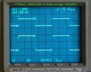
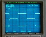
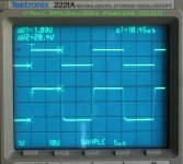
The pics below show a 20Vp-p square wave, with no Zobel installed, with and without a load.
First Pic: 50KHz, 20Vp-p, no Zobel, no load.
Second Pic: 50KHz, 20Vp-p, no Zobel, 7.5R||0.2uFd
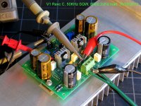
Third Pic, as tested: +-30.5V bench supply, input filter, KSC3503E/KSA1381E with 47pF Miller caps, no Zobel on circuit board
The pics below show a 20Vp-p square wave, with no Zobel installed, with and without a load.
First Pic: 50KHz, 20Vp-p, no Zobel, no load.
Second Pic: 50KHz, 20Vp-p, no Zobel, 7.5R||0.2uFd
Third Pic, as tested: +-30.5V bench supply, input filter, KSC3503E/KSA1381E with 47pF Miller caps, no Zobel on circuit board
Attachments
Last edited:
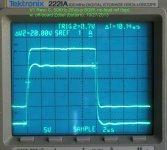
Test Results, 50KHz Sq Wave, Zobel off-board
First pic: No load, no Zobel
Second Pic: 7.5R 0.1uFd in series, and no other load
The two pictures show very little difference, although there is a slight one.
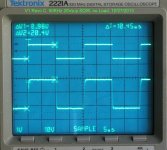
Third pic: Magnified no load saved waveform used as reference (top trace), for waveform with Zobel (bottom trace), showing the Zobel-loaded output a little more clearly. Not an especially fair comparison in any case, because it includes fairly long leads between the board and the load.
First pic: No load, no Zobel
Second Pic: 7.5R 0.1uFd in series, and no other load
The two pictures show very little difference, although there is a slight one.
Third pic: Magnified no load saved waveform used as reference (top trace), for waveform with Zobel (bottom trace), showing the Zobel-loaded output a little more clearly. Not an especially fair comparison in any case, because it includes fairly long leads between the board and the load.
Attachments
Last edited:
Thanks for the pictures and the tests. Very useful!
I see the effect, but it is really benign and probably as a result of the wires to the load. If you twist them it may disappear completely. Mine is closer to Lazy's, slightly less, may be... Hmm, I should try some changes in the power supply, unless the 2SK/2SJ are completely different animal than my FETs, but I doubt it.
I see the effect, but it is really benign and probably as a result of the wires to the load. If you twist them it may disappear completely. Mine is closer to Lazy's, slightly less, may be... Hmm, I should try some changes in the power supply, unless the 2SK/2SJ are completely different animal than my FETs, but I doubt it.
Not in this regard, I think. The load was connected using test leads, and not hookup wire. You can see a red and black clip in the third pic. They are about 3 feet long, and they were loosely twisted. not tightly like you would do inside a chassis, just a few turns to keep them together....unless the 2SK/2SJ are completely different animal than my FETs, but I doubt it.
I am wondering if the "ringing" may increase when the size of the Miller caps at the VAS is decreased. (some people use 24pF, or even 12, and I am testing with 47pf)
I can use the through-hole version of VSSA without the Zobel just fine, but my speaker wires are just a few feet long, and other people may not be able to do that. In other words, if we know that just moving around 3-4 foot leads can make the ripple bigger or smaller, then we can conclude that with no Zobel near the source, and long leads from amp to speaker load, it might get quite... ummmm "interesting".
In any case, I am not sure that what we are seeing here meets the classic definition of ringing. When the test equipment changes what you are trying to measure, we used to call it Phantom Readings....
My layout, as promised.
Some components aren't standard, for instance input cap is very big (RM 37,5). I've made peeceebee according to components I already had at home. Basically, it's shaan's peeceebee.
Hi all,
Does someone used this Peeceebee version of Dobrivoje. can I use this to build a amplifier
peeceebee
Hi PMI very good results!
Is this from version of page ?http://www.diyaudio.com/forums/solid-state/231662-peeceebee-40.html#post3490152
post#393?
Regards.
Thimios.
First pic: No load, no Zobel
Second Pic: 7.5R 0.1uFd in series, and no other load
The two pictures show very little difference, although there is a slight one.
Third pic: Magnified no load saved waveform used as reference (top trace), for waveform with Zobel (bottom trace), showing the Zobel-loaded output a little more clearly. Not an especially fair comparison in any case, because it includes fairly long leads between the board and the load.
Hi PMI very good results!
Is this from version of page ?http://www.diyaudio.com/forums/solid-state/231662-peeceebee-40.html#post3490152
post#393?
Regards.
Thimios.
Hi all,
Does someone used this Peeceebee version of Dobrivoje. can I use this to build a amplifier
Hi Thimios & Sidebyside,Hi friends
I want to come in through hole version of this amplifier but this time i'm confused
at all.
Can anybody say ...which is the most recommended version?
Where i can find the pcb pdf?
Where i can find shematic?
Thanks to all.
Best regards.
Thimios.
welcome to the six transistor magic
Do you read post #1?
there are some link to all version that has been tested.
There are so many version because we make a PeeCeeBee according to components that we already had at hand
the most different is the mounting style on your own heat sink
It is your choice which one to be build.
the result must be similar...
There are offset trimmers to set DC-offset & bias.
I don't use it because I matched the parts except the output FET's
(not so close matched btw
)If you can just match the input pair, VAS transistor, 2k2, 100, & 15k-18k(or other value depending on supply rails)...
Regards
John
Last edited:
Hi Pete, I wish I have a scope too...Not in this regard, I think...
I am wondering if the "ringing" may increase when the size of the Miller caps at the VAS is decreased. (some people use 24pF, or even 12, and I am testing with 47pf)
....
it might get quite... ummmm "interesting".
Can you try it with higher than 47pF or lower than that...
that might very interesting to know, by me at least
I use 33pF by now (was 22pF)
So we know the limit of VAS caps that will safe or too "much" to used.
Also what happen
to the signal if I use 100pF or any value else, cause I only have 68 & 100pF (no good quality 47pF at me )Thanks in advance.
peeceebee
Has anyone test with these fets. 2SK1530 & 2SJ201?
Thanks.
Thanks again John .Hi Thimios & Sidebyside,
welcome to the six transistor magic
Do you read post #1?
there are some link to all version that has been tested.
There are so many version because we make a PeeCeeBee according to components that we already had at hand
the most different is the mounting style on your own heat sink
It is your choice which one to be build.
the result must be similar...
There are offset trimmers to set DC-offset & bias.
I don't use it because I matched the parts except the output FET's
(not so close matched btw
If you can just match the input pair, VAS transistor, 2k2, 100, & 15k-18k(or other value depending on supply rails)...
Regards
John
Has anyone test with these fets. 2SK1530 & 2SJ201?
Thanks.
I guess yes but in another thread...Thanks again John .
Has anyone test with these fets. 2SK1530 & 2SJ201?
Thanks.
Here we only use Lateral Fets, that one you mention is not lateral one.
You can go here http://www.diyaudio.com/forums/solid-state/237219-fet-hex-explendit-amplifier.html for other type fet's output or BJT too
They need temp-co compensation
but with Latfet's we don't need that, so this one is simpler to build...
Last edited:
- Home
- Amplifiers
- Solid State
- PeeCeeBee