Terry,
There's no issue with the output device temperature based on what you are experiencing.
I'm very happy to hear you are enjoying it and that I was able to be part of that.
It is possible that little bit of 'crispness' might be the slightest bit of clipping when you are playing loudly. Amps with lateral MOSFET output stages are not as voltage efficient (that is there's more 'loss') than amplifiers with BJT output stages. They simply can't get as close to the power rails. In this case you are 'loosing' anywhere from 8V to 12V off each rail, depending upon load. With your supply voltages the output should be clean to about +/-27V of output on your 4Ω speakers, so about 90W average output (to say RMS is a misnomer) maximum. I'm not too familiar with your speakers so I don't know how efficient they are, but that definitely plays a role as does their worst case impedance.
I know with my PeeCeeBee, running on +/-31.5V supplies into a nominal 6Ω speaker (that has an impedance dip down to just over 3Ω) with an efficiency of 93dB/W@1m can cleanly play to a level I will only tolerate for a couple of songs. Otherwise at 'normal' levels there is no issue, even with fairly dynamic materials.
Jason
The speakers I am using are;
JBL 4311
JBL 4412
JBL 4425
They are rated at about 90-91db. Each pair have their own distinct sound. I will typically try each new amp through each as each one will highlight a different part of the spectrum. I was pushing the peecceebee intentionally to kind of see what it's limits were. I'm reasonably certain that the "crispness" I am hearing is clipping. I was A/Bing it against the DX Super A in the picture above. They are running off identical transformers. The peeceebee is using a CM and the Super A the regulated supply designed for it. Both are dialed down to +/-36Vdc rails. The Super A gets louder before clipping. It has two pair MJLxxxx outputs so that probably explains that. They both sound very pleasant at listening levels.
Looks like I am right where I should be with the temps so I will leave things alone and finish building a case for it.
Blessings, Terry
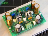
It's alive...
First board assembled last night!
(or rather, this morning, )
)
Successfully powered up and calibrated off my bench supply. First quick sine wave and square wave sweeps done, and looking good from about 10Hz to 50KHz. Frequency response looks perfectly flat from below 10Hz to above 50KHz, with no phase delay at all...
I'll post some first pics, but no real measurements yet, I hope to have those by this weekend.
First board assembled last night!
(or rather, this morning,
)Successfully powered up and calibrated off my bench supply. First quick sine wave and square wave sweeps done, and looking good from about 10Hz to 50KHz. Frequency response looks perfectly flat from below 10Hz to above 50KHz, with no phase delay at all...
I'll post some first pics, but no real measurements yet, I hope to have those by this weekend.
Attachments
I do not need them for the first tests. They are expensive and I don't have spares, so in case I had to build another board right away, I left them off.I see you left off C17 & C18. Are those not needed?
According to Shaan, none of the parallel film caps are required (with some assumptions about noise, I am sure). And some people do not believe in bypassing electrolytics with film caps at all.
The circuit board has space for the same caps as LC specified, as of V1.4 of his schematic, and associated BOM. There are some extra pads at some of the cap locations, so parts with different spacings can be substituted (both 5 and 7.5 mm lead spacing, etc).
Test Results, basic sine and square wave sweeps
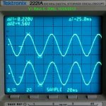
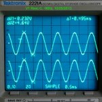
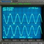
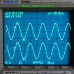
Pics 1-4, simple bandwidth test, 20Hz to 50KHz.
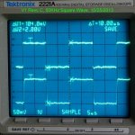
Last Pic, 50KHz square wave.
-3db points look like they are below 5 Hz and above 500KHz. Measuring that accurately will require a little more fiddling with the Wavetek signal generator. Below and above normal audio range, in any case (unless you are a dog... )
The 50KHz square wave is just starting to show rounded edges. Scope pic also shows about 10 millivolts of noise on the input signal, when the grounds for the signal generator and scope are far apart.
Pics 1-4, simple bandwidth test, 20Hz to 50KHz.
Last Pic, 50KHz square wave.
-3db points look like they are below 5 Hz and above 500KHz. Measuring that accurately will require a little more fiddling with the Wavetek signal generator. Below and above normal audio range, in any case (unless you are a dog...
)The 50KHz square wave is just starting to show rounded edges. Scope pic also shows about 10 millivolts of noise on the input signal, when the grounds for the signal generator and scope are far apart.
Attachments
Pete, you are fast...
I see ccs (no ccs for PeeCeeBee as Shaan don't like it)
tell me if it is not difficult to set,
& why the measurement don't look so good?
The bias is not set properly yet?
My power supply board etched last night too... (00:30 AM)
today is time to drilling some hole so I can use it to power up the double pairs
Regards
John
CCS is optional on this circuit board. I do not take sides in this.Pete, you are fast...
I see ccs (no ccs for PeeCeeBee as Shaan don't like it)
tell me if it is not difficult to set,
& why the measurement don't look so good?
The bias is not set properly yet?
My power supply board etched last night too... (00:30 AM)
today is time to drilling some hole so I can use it to power up the double pairs
Regards
John
I look forward to the details of your build,
Everything "looks" good here, and sounds excellent, but making good measurements takes time.
The amp has a flat frequency response from 10Hz to well above 50KHz, probably to 300KHz, I think.
Making measurements below 10 Hz, and above 500KHz is difficult with my equipment. Below 10Hz and above 400kHz, my waveform generator is hard to adjust, probably because it is very old. I prefer to make measurements at a small signal level, so that makes it a bit harder, when the gain is around 27db, and I just did not have enough time.
Test conditions and bias:
Supply voltage: ~ +/-30.5V (bench supply for testing)
Zobel not installed yet
Miller compensation caps: 47pF
VAS bias: 13 ma (KSA1381E/KSC3503E) close to what LC specified
KSA1381E and KSC3503E matched for hfe within 5%
Gain: ~26.5db, 10Hz - 50KHz
Front end bias: ~1.9 mA
Offset at Output: 0V+/-3mV
Total idle current: 150mA
(this will be ~180mA at +/-36V supply voltage)
Power @ idle: 9~9.5W/channel
(will be ~13W at +/-36V supply voltage)
Room Temp: ~24C
VAS heatsink: 39C
Main heatsink: 32C
(Temps measured with heatsink flat on the table, which is worst case)
Heatsink temperature is consistent with heatsink rating, 0.65C/watt, free air, and restricted air flow because the fins are facing down. At +/-36V supply, the heatsink will be about 10C above room temperature.
Last edited:
Good question, I wish there was more discussion about component selection, etc.Hi Pete. You mention a zobel. What are you guys using for that?
Thanks, Terry
Personally, I can get away with one 10R/0.5W resistor and a 0.1uF film cap, at a 35V supply voltage. However, most people should probably have 10R/1W.
For convenience (and compatibity with the VSSA SMD modules), my board is laid out for a split Zobel, meaning 2 resistors and two caps in parallel. Resistor lead spacing can be either 10 or 12 mm.
You can also get Vishay/Dale 10R/1W resistors which are the length of a conventional 1/4 W, but those may not be available locally to everyone (ex: CPF110R000FKE14), and expensive compared to a conventional 1/4W or 1/2W.
Some people will just leave the Zobel off the amplifier pcb, and put one off-board, at the back panel. I believe Shaan intended for the Zobel to be off-board, but I can't remember if he did not actually specify one.
Now that I think about it, I haven't used a Zobel since I built the Superamp. Is this something I should be using on all my amps?
I think all of the amps I built used an inductor except this one and the Symasym. What is the reason this amp doesn't need it.
Thanks, Terry
I think all of the amps I built used an inductor except this one and the Symasym. What is the reason this amp doesn't need it.
Thanks, Terry
The Zobel keeps the amplifier 'seeing' a load resistance at very high frequencies where a real-world speaker may appear as a high impedance, and can also assist with 'trapping' high frequencies coming in.
The output inductor is another defence against RF hash from entering the amplifier. It can also quell the ringing sometimes seen on an oscilloscope trace, though a little ringing isn't necessarily an actual problem.
Most amplifiers will use a Zobel but some are fine without. An amplifier should be designed such that the damped inductor is optional, IMHO. Really depends on the load connected and environment the amplifier is in.
@Jason: Speaking of RF and high frequency in general...
Although the circuit is remarkably stable and well behaved, it can oscillate under some conditions. I observed this during testing last time, when it looked like I picked up some RF when I left a long open (unconnected and unterminated) input lead. It may have led to frying the output and VAS transistors on one rail (while I was admiring the waveform on my scope )
So I am wondering if the input filter should be set intentionally lower than it is now. Having a 1 megaherz bandwidth is impressive on one hand, but may not be good for safety on the other.
Although the circuit is remarkably stable and well behaved, it can oscillate under some conditions. I observed this during testing last time, when it looked like I picked up some RF when I left a long open (unconnected and unterminated) input lead. It may have led to frying the output and VAS transistors on one rail (while I was admiring the waveform on my scope
)So I am wondering if the input filter should be set intentionally lower than it is now. Having a 1 megaherz bandwidth is impressive on one hand, but may not be good for safety on the other.
VAS current at 50VDC
My PSU is done &
I've try to use the double pairs at +/-50VDC (47VDC, measured).
I have 115mV on 10 ohm emitter so about 11.5mA on VAS transistor but they are so hot.
Also I guess it start to make some oscillation at higher voltage, I use 22pF comp-caps & zobel is there on the board...
How to decrease the VAS current but we can still increase the bias?
Any though?
& I really don't know if it is 1/2 oz or less
Maybe if you show your board there will be more comment on it
Regards
My PSU is done &
I've try to use the double pairs at +/-50VDC (47VDC, measured).
I have 115mV on 10 ohm emitter so about 11.5mA on VAS transistor but they are so hot.
Also I guess it start to make some oscillation at higher voltage, I use 22pF comp-caps & zobel is there on the board...
How to decrease the VAS current but we can still increase the bias?
Any though?
Rick, I made my own board & the bottom is so fatJohn,
A question for you or anyone else. Do you use 1oz or 1/2oz copper plated boards & Does it make a Difference for an Amplifier board. I have just tried Both and the 1/2oz looks & feels lightweight for carrying this current. Any thoughts?
& I really don't know if it is 1/2 oz or lessMaybe if you show your board there will be more comment on it
Regards
Last edited:
Yes. 10R, 0.1uFd.Hi Guys,
I'm not sure I got an answer. Should I be using a Zobel with the peeceebee? If so, what values for the resistor and cap?
Thanks, Terry
http://www.diyaudio.com/forums/solid-state/231662-peeceebee-143.html#post3680220
- Home
- Amplifiers
- Solid State
- PeeCeeBee