Hi Jason,
Do you have a silk screen shot that shows the location of the OFF1, Off2 and Bias resistors?
Thanks, Terry
There should be a parts location diagram in the box with the boards, no? If not it has been previously posted and I'm pretty sure Shaan linked to my 'reference' post in post #1 here. There were two versions dependant on the input transistors chosen, but otherwise the boards were identical.
The center distance between those two holes is the same, so you may be able to use the same mounting holes.Pete,
Is the distance between Latfet holes on the new pcb the same as on the previous board so that the heatsinks for the previous board can be used for the new as well?
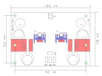
The board outline is 102x70 mm, compared to 102x64 before. The corner hole locations are different by that amount.
I did not actually use those, even though I designed for them.
There should be a parts location diagram in the box with the boards, no? If not it has been previously posted and I'm pretty sure Shaan linked to my 'reference' post in post #1 here. There were two versions dependant on the input transistors chosen, but otherwise the boards were identical.
I'm sorry, you're right, it's there. I didn't look close enough. I'll get started on this today. Shouldn't take long. I have a cap multiplier for it already.
Blessings, Terry
I look forward to seeing more of these!This is some information I compiled to assist a fellow member construct the TO-3 version of the PeeCeeBee. I thought it might benefit someone who needed a little added guidance with this specific project. Should someone find an error, please let me know so I can correct it.
With that in mind, it might be worth noting that some people using the original VSSA modules have had to replace the 10R which is in series with the rail diodes with something higher power than 1/4 W.
Terry won't have that issue with the CM supply because a soft-start is inherent in the design. Others might. If the supply voltage comes up fast enough, the startup current to charge the 1000uF cap can be large. (Shaan originally used a smaller cap, and a lower supply voltage, so this was not a problem.)
The TO-3 version might appeal to people with aspirations to more power per channel, therefore higher supply voltage, and more inrush into that 1000uF.
Btw, and more recently, LC has recommended eliminating the series D-R completely in the main VSSA thread.
I look forward to seeing more of these!
With that in mind, it might be worth noting that some people using the original VSSA modules have had to replace the 10R which is in series with the rail diodes with something higher power than 1/4 W.
Terry won't have that issue with the CM supply because a soft-start is inherent in the design. Others might. If the supply voltage comes up fast enough, the startup current to charge the 1000uF cap can be large. (Shaan originally used a smaller cap, and a lower supply voltage, so this was not a problem.)
The TO-3 version might appeal to people with aspirations to more power per channel, therefore higher supply voltage, and more inrush into that 1000uF.
Btw, and more recently, LC has recommended eliminating the series D-R completely in the main VSSA thread.
The LC VSSA had a parts substitution by the board assembler that was not approved by LC. LC had chosen a pulse rated resistor and the substitute wasn't pulse rated. It only seemed to be an issue with SMPS units like the modified Hypex, as LC recommended, due to the near instantaneous appearance of the rails at full voltage. On a CM or plain old linear supply this shouldn't be an issue even for a 1/4W part. Of course one can install a higher rated part if desired. I haven't had any issues with the 1/4W CF resistor of my initial build.
As for eliminating the diode and resistor, for our resistively loaded version I think it is wise to leave it in to improve PSRR, but in LC's VSSA with the CCSs it seems to benefit from the local small reservoir provided by bypassing the D-R.
My

Last edited:
Good point....
As for eliminating the diode and resistor, for our resistively loaded version I think it is wise to leave it in to improve PSRR, but in LC's VSSA with the CCSs it seems to benefit from the local small reservoir provided by bypassing the D-R.
My
I did not have an issue with the 1/4W, because I am not using the Hypex supply, but I think it is worth considering depending on the circumstances.
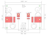
I am attaching a couple pics that show the locations of all the mounting holes on the new board. The first pic is the version with VAS transistors and small heatsinks top-side, same configuration that you and I are using now. The second pic is with the VAS transistors under the board. There is a total of 8 holes, four in the corners, 2 for the Latfets, and 2 for the VAS transistors if mounted on the main heatsink. Hopefully nobody will try to use all eight at the same time...Pete,
Is the distance between Latfet holes on the new pcb the same as on the previous board so that the heatsinks for the previous board can be used for the new as well?

Attachments
I agree, but the board can still be used with those, even though space around the part will be smaller. Pads for protection diodes have been added for the Alfets, which apparently do not have internal ones. Sadly the incremental cost is a bit more than 2 cents...My 2 cents : the perfection would be to find place for TO264package and associated hole => Alffet and excicon 16A devices....
Marc
A TO-264 package will fit with the mounting hole just outside the board, and the board will use at least two of the corner mounting holes to keep it in place. I moved some of the parts around so there would be a little more room around the TO-3P outline, and TO-264 will use all of that.
The double-die parts are one of the things that prompted the option to mount the VAS transistors on the main heatsink. I also made sure I had the 2SC3503E on hand for people who want to use a supply voltage over 35V, at least for the first few dozen boards.
TO-3P and TO-247 are almost identical, and the pads have been moved a bit and enlarged compared to the last version, to make it easier for both to fit.
The holes have been made larger for the TO-264 leads. Using the double-die parts implies a higher supply voltage, so the voltage specs for the caps and for the input stage transistors have to be higher also. If using the top-side VAS heatsink, one of the larger (or taller) versions will probably have to be used.
I agree, but the board can still be used with those, even though space around the part will be smaller. Pads for protection diodes have been added for the Alfets, which apparently do not have internal ones. Sadly the incremental cost is a bit more than 2 cents...
A TO-264 package will fit with the mounting hole just outside the board, and the board will use at least two of the corner mounting holes to keep it in place. I moved some of the parts around so there would be a little more room around the TO-3P outline, and TO-264 will use all of that.
The double-die parts are one of the things that prompted the option to mount the VAS transistors on the main heatsink. I also made sure I had the 2SC3503E on hand for people who want to use a supply voltage over 35V, at least for the first few dozen boards.
TO-3P and TO-247 are almost identical, and the pads have been moved a bit and enlarged compared to the last version, to make it easier for both to fit.
The holes have been made larger for the TO-264 leads. Using the double-die parts implies a higher supply voltage, so the voltage specs for the caps and for the input stage transistors have to be higher also. If using the top-side VAS heatsink, one of the larger (or taller) versions will probably have to be used.
That's good news and made the board more perfect to my eyes...really good job Peter
 .
.Marc
Thank you, Marc!That's good news and made the board more perfect to my eyes...really good job Peter
Marc
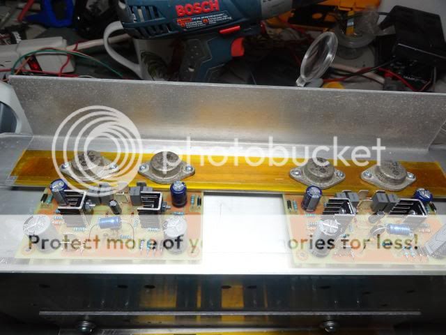
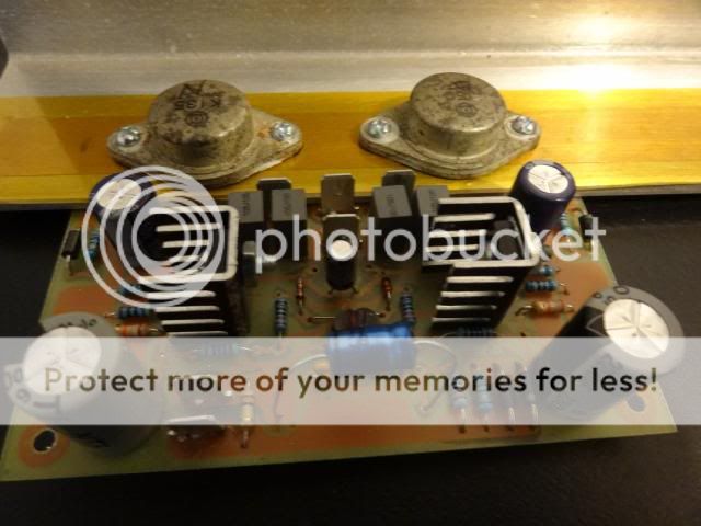
It's Alive!!!
Hey Jason,
I have it playing music. You were right. This is a VERY good sounding amp. I didn't even build it with the best parts. I used what I had on hand. Instead of the 1000uf caps I used 330uf, 50V. I didn't have a nice WIMA 10uf for the input. All I had was a non-polar 10UF 100V electo so I threw those in there just so I could try it. I just might leave them, this things sounds awesome! I played Jazz, country, techno and rock through it and I couldn't believe how true it sounded. Probably the best all around amp I've built. I can't wait to get it into a cabinet so I can really test it out.
Thanks so much!
Blessings, Terry


Last edited:
Smartx, do you mean the to-3 one right?
they will survive for next decade or more if you can find it
Hi Terry,
congratulation nice build,
that to-3 seems so robust &
now you can enjoy the magic sound of it...
This is 6 transistors magic that we are talking & building here,
now you know why it worth to try.
Make sure nothing is not too hot & DC offset is low
The 330uF/50v is fine as you use caps multiplier.
I don't see any dc offset trimmer maybe you don't need it either
Also at what voltage & bias current do you operate on them?
Regards
John
they will survive for next decade or more
if you can find itHi Terry,
congratulation
nice build, that to-3 seems so robust &
now you can enjoy the magic sound of it...
This is 6 transistors magic that we are talking & building here,
now you know why it worth to try.
Make sure nothing is not too hot & DC offset is low
The 330uF/50v is fine as you use caps multiplier.
I don't see any dc offset trimmer maybe you don't need it either
Also at what voltage & bias current do you operate on them?
Regards
John
Smartx, do you mean the to-3 one right?
they will survive for next decade or more
Yes! I dream of finding two pairs of them, whatever their age!
Two pairs = VSSA!
Six pairs = Goldmund (I've got Alex's boards!)
Congrats to Terry, that is able to build several kinds of amps at the same time, keeping motivation alive!

It's Alive!!!
Hey Jason,
I have it playing music. You were right. This is a VERY good sounding amp. I didn't even build it with the best parts. I used what I had on hand. Instead of the 1000uf caps I used 330uf, 50V. I didn't have a nice WIMA 10uf for the input. All I had was a non-polar 10UF 100V electo so I threw those in there just so I could try it. I just might leave them, this things sounds awesome! I played Jazz, country, techno and rock through it and I couldn't believe how true it sounded. Probably the best all around amp I've built. I can't wait to get it into a cabinet so I can really test it out.
Thanks so much!
Blessings, Terry
Fantastic! Glad to hear you were impressed with it, given the sheer number of other amplifiers you have built it's good to hear it runs with the best of them. Seems you didn't have any issue getting things up and running either.
Got to say the outputs look like they have been around for a while too.
Anyhow, get it fully tested and give it a good listening session in your usual listening environment. I look forward to your listening impressions. Seems no matter which amplifier I hook up I always come back to PeeCeeBee.
I just etched a second set of boards for myself and will be building one with nicer parts just to see if it matters
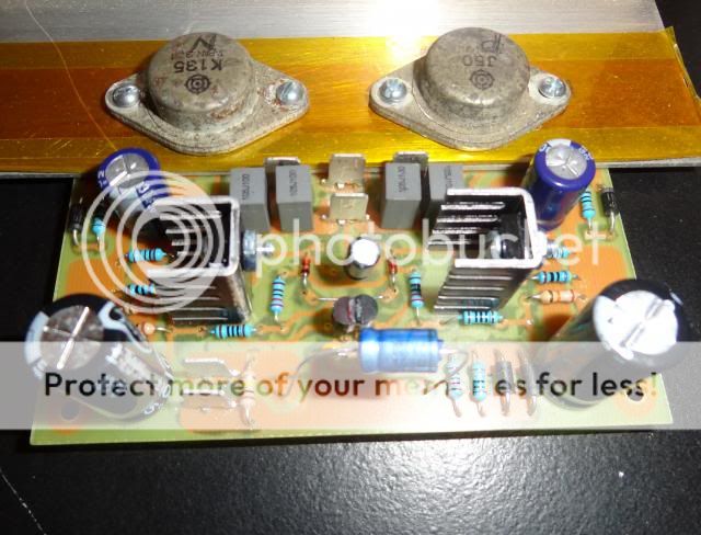
.He, he, did you get good look at those MOSFETs? Those came from an old Soundcraftsmen that I bought off Ebay as a parts amp that I thought I could fix. I think it went through a flood. The VAS transistors had legs that were completely gone. Well I never got it working so I just threw it out in the shed. When Jason offered to make some boards for me I started looking online for some outputs and couldn't really find any that weren't very expensive and who know if they were even real. Then I remembered the old Soundcraftsmen. I pulled the outputs and they all measured good. They look bad but they were bolted in with grease so the mating surfaces were clean. They sound really lovely. I have to say I was a bit surprised though to be fair, the Soundcraftsmen amps sound very good.
When I fired them up, they were each running at 121ma per rail with no bias resistor. One of them had 2mv offset and the other had 31mv offset. I tried hooking a pot up in place of the bias resistor but all it would do is lower the bias, not raise so I just left it alone at 121ma. Then I hooked up a 1M post to the OFF1 of the board that had too much offset. Turns out that 1m was perfect so I installed a 1m resistor there and now that channel has -3mv offset. This makes me want to investigate the first boards I tried and see if I can track down the problem.
Blessings, Terry
Well I never got it working so I just threw it out in the shed. When Jason offered to make some boards for me I started looking online for some outputs and couldn't really find any that weren't very expensive and who know if they were even real. Then I remembered the old Soundcraftsmen. I pulled the outputs and they all measured good. They look bad but they were bolted in with grease so the mating surfaces were clean. They sound really lovely. I have to say I was a bit surprised though to be fair, the Soundcraftsmen amps sound very good.When I fired them up, they were each running at 121ma per rail with no bias resistor. One of them had 2mv offset and the other had 31mv offset. I tried hooking a pot up in place of the bias resistor but all it would do is lower the bias, not raise so I just left it alone at 121ma. Then I hooked up a 1M post to the OFF1 of the board that had too much offset. Turns out that 1m was perfect so I installed a 1m resistor there and now that channel has -3mv offset. This makes me want to investigate the first boards I tried and see if I can track down the problem.
Blessings, Terry
Hi Thiagomogi,Hello guys, does buz900d/buz901d serves this amp?
yes you can use any lateral mosfet, that one must be replacement for the old to-3 one...
You can build the one like Terry/still4given done, layout by Jason post #405 all you need is there.
Or you can build the one with J162/K1058 like me
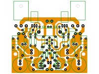
... btw, this is my new PeeCeeBee for easy mounting on heatsink.
Not tested yet, but if you want you can try it
see attachment!
Anyhow, get it fully tested and give it a good listening session in your usual listening environment. I look forward to your listening impressions. Seems no matter which amplifier I hook up I always come back to PeeCeeBee.
I just etched a second set of boards for myself and will be building one with nicer parts just to see if it matters
Hi Jason,
Same with me...
I will build again too...
with nicer parts too I guess
& I guess it matters a bit Regards
John
Edit:
the new layout use serial trimmer resistor so this one easier to set DC offset(tested when my last build)...
You only need very low value 100-500 ohm trimmer, can use cheap one & replace with resistor when everything fixed.
Please double check also cos I don't build it yet
Attachments
Last edited:
- Home
- Amplifiers
- Solid State
- PeeCeeBee