@Nikosokey - You had to remove the ground loop breaker by the looks of it. Simply replacing the 10 ohm resistor with a link didn't do the trick? Looks like there are some other modifications as well; would you care to elaborate on what you have done? I'm curious to get additional information.
I haven't bothered to scope mine as yet. Finally unhooked it so I can begin to build a chassis for it. Perhaps some tests when it is on a dedicated PSU and in a chassis.
I haven't bothered to scope mine as yet. Finally unhooked it so I can begin to build a chassis for it. Perhaps some tests when it is on a dedicated PSU and in a chassis.
Hello
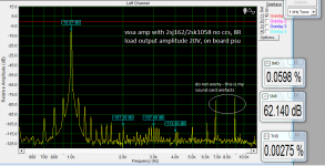
I did small measurement today. Looks very good as only there is 6 transistors in the amp.
If I can ask, can someone explain me the advantage and disadvantage of separiting the signal gnd by the resistor (10r) please. I am working on another board and I have lack of knowlage in that subject.
THX
I did small measurement today. Looks very good as only there is 6 transistors in the amp.
If I can ask, can someone explain me the advantage and disadvantage of separiting the signal gnd by the resistor (10r) please. I am working on another board and I have lack of knowlage in that subject.
THX
Attachments
Hello
I did small measurement today. Looks very good as only there is 6 transistors in the amp.
If I can ask, can someone explain me the advantage and disadvantage of separiting the signal gnd by the resistor (10r) please. I am working on another board and I have lack of knowlage in that subject.
THX
Nice. That shows minuscule amount of THD+IMD. Great job.
I'm no expert but I think what the resistor does is preventing a ground loop to form with fully earthed source and amp system. To its disadvantage the AC impedance of the input at RF range is no longer zero, i.e. 10R in series with the input lowpass filter network to ground, causing some RF interference to get its way into the main amplifying stages resulting in audible/inaudible anomalies like noise and distortion. To solve this just place a 100nF cap in parallel with the resistor and all is well.
Hello
I did small measurement today. Looks very good as only there is 6 transistors in the amp.
This is an extraordinary achievement for any amplifier generally speaking and this is also what listening tests confirms on daily basis at all DIY-ers who already assembled this amp.

@Damanhuri use it to make one channel VSSA if you no sure yet...
Even with one channel you can feel 3D of sound that what my brother say too") we've listen to it together
we've listen to it together
Buruan rakit kang Daman !!!
There so much very nice measurement up here but I don't have scope
btw now my PeeCeeBee tested with low freq response & the bass is very good, its very loud now
& controlled bass too...
I'm shocked it's more than what I expected
it's only feed by +/- 33 VDC
Even with one channel you can feel 3D of sound that what my brother say too
we've listen to it togetherBuruan rakit kang Daman !!!
There so much very nice measurement up here but I don't have scope
btw now my PeeCeeBee tested with low freq response & the bass is very good, its very loud now
& controlled bass too...
I'm shocked it's more than what I expected
it's only feed by +/- 33 VDC
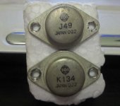
hi kang daman, where you get those fet?
See post #388 (http://www.diyaudio.com/forums/solid-state/231662-peeceebee-39.html)
Regards zeoN_Rider
kang naf your VSSA feed by about +/- 40-42VDC right?
If you try lower voltage 33-35VDC you can raise the bias to optimum level, total bias about 200mA, don't forget to monitor the heat sink!
maybe you think the output will be not enough with lower voltage but just try it
higher voltage not always sound better
Btw maybe you can make your SMPS project with multiple output voltage to feed your PeeCeeBee,
Lower voltage to use with higher bias,
higher voltage to use with lower bias
Waiting to next your VSSA with new SMPS PSU
Regards
my friend offered it to mehi kang daman, where you get those fet?
Mono???
Yeah Mono, I do not have a partner anymore: (
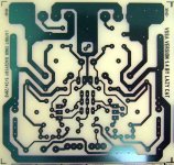
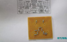
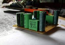
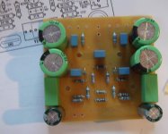
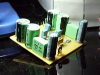
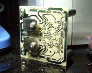
Here is my version of peeceebee
Still on the making
approximately how many watts it will produce for +-35V?
Still on the making
approximately how many watts it will produce for +-35V?
Attachments
Here is my version of peeceebee
Still on the making
approximately how many watts it will produce for +-35V?
Very very gooood !

Congratulations Dacz, enjoy in the music.

60 Wrms/8 Ohm
- Home
- Amplifiers
- Solid State
- PeeCeeBee