Decreasing the gain is usually easier than increasing it. I am testing my boards with a gain of 10, and that is plenty for me at the moment, because I am testing with digital sources (CD layer, DAC etc.). I simply changed the 2.2K resistor.I was wondering about using a low power (small signal) version of the VSSA with perhaps a gain of 2 or 3. Any thoughts?
The most obvious way to decrease gain is using a volume control pot, or a resistor divider, with a buffer (like the B1 featured prominently in the Pass labs forum, or a simple diamond buffer).
I am curious why you want such a low gain?
...I need more gain, can you suggest any preamp to connect...
The DOZ preamp.
I believe he means how if we use VSSA with lower voltage lower gain as a preamp, without the lateralI am curious why you want such a low gain?
")
Ok, will try that thanksThe DOZ preamp.
@PMI I try direct from PC & 8 ohm speakers, try DVD player too same result...
maybe the speakers is not so good & I don't have any good preamp
btw here at my testing place is a little crowded one & at night it's a different story
Last edited:
Ok, understood.I believe he means how if we use VSSA with lower voltage lower gain as a preamp, without the lateral
How about just posting a schematic of the front parts in the other forum, someone will simulate it for you, critique it, and post suggested corrections before you even know it. There are people posting there with some amazing knowledge! (well, amazing to me, anyway)@PMI - I was making the suggestion of using the VSSA as the basis for a preamp, should someone desire it. Sounds like something to sim...
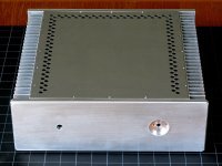
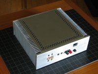
Pee-Cee-Bee Chassis
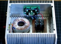
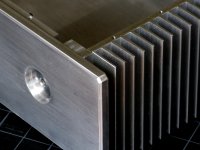
Prototype of my new chassis, work in progress. Outside dimensions are about 12.25 W x 11.75 D x 4.0 H (310 x 200 x 254 mm). Inside dimensions 9.75 x 10.75 x 3.9
( 250 x 273 x 98 mm). Just large enough for a 4.5~5" diameter transformer, and power supply board that fits into a 5x9" space, allowing some room for wiring.
All aluminum, except top and bottom plates are 16-ga stainless.
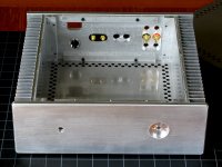
Aluminum parts are made like an erector set, so any one part can be removed without disassembling the whole chassis. One of the cover plates, top or bottom has to remain attached, but other than that, front, back, or either of the two sides can be removed individually. The sides are nothing more than heatsinks from one of the companies that supports this forum with their advertising, Heatsink USA.
Not quite the final version, and none of the parts have their final finish. As usual I plan to make more than one, so comments & suggestions welcome. Nothing cast in concrete... I mean, aluminum, yet, and I am still planning to move some of the machine screws for good access.
@ John, no I did NOT cut and shape the parts myself, you are still the DIY metal work champ here...
Prototype of my new chassis, work in progress. Outside dimensions are about 12.25 W x 11.75 D x 4.0 H (310 x 200 x 254 mm). Inside dimensions 9.75 x 10.75 x 3.9
( 250 x 273 x 98 mm). Just large enough for a 4.5~5" diameter transformer, and power supply board that fits into a 5x9" space, allowing some room for wiring.
All aluminum, except top and bottom plates are 16-ga stainless.
Aluminum parts are made like an erector set, so any one part can be removed without disassembling the whole chassis. One of the cover plates, top or bottom has to remain attached, but other than that, front, back, or either of the two sides can be removed individually. The sides are nothing more than heatsinks from one of the companies that supports this forum with their advertising, Heatsink USA.
Not quite the final version, and none of the parts have their final finish. As usual I plan to make more than one, so comments & suggestions welcome. Nothing cast in concrete... I mean, aluminum, yet, and I am still planning to move some of the machine screws for good access.
@ John, no I did NOT cut and shape the parts myself, you are still the DIY metal work champ here... Attachments
Damn, look at that bbox!
Wow... nice box..
Thanks, I am hoping to make a couple small revisions before I wire it all, and looking forward to getting all the bits off the bench and into the chassis...
A few more tests... Finding the high frequency -3db point
Caution: All of the tests were done without a zobel network. At high frequency, a normal-value Zobel resistor might get VERY hot during a high frequency test.
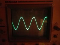
First three pictures are finding the -3db point.
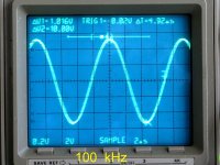
#1 - 100 kHz since wave, input and output in phase, no attenuation.
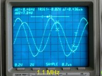
#2 - 1.1 MHz, -2db
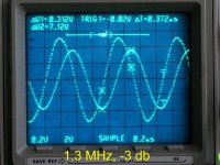
#3 - 1.3 MHz, -3db
In the first pic, the two channels of the o-scope were adjusted to different scales to show the input and output signal superimposed at 100KHz, well before any high frequency rolloff. Second pic, getting close. Third pic, -3db point reached at about 1.3 MHz. Conclusion, there is plenty of bandwidth, well above the audio range.
Caution: All of the tests were done without a zobel network. At high frequency, a normal-value Zobel resistor might get VERY hot during a high frequency test.
First three pictures are finding the -3db point.
#1 - 100 kHz since wave, input and output in phase, no attenuation.
#2 - 1.1 MHz, -2db
#3 - 1.3 MHz, -3db
In the first pic, the two channels of the o-scope were adjusted to different scales to show the input and output signal superimposed at 100KHz, well before any high frequency rolloff. Second pic, getting close. Third pic, -3db point reached at about 1.3 MHz. Conclusion, there is plenty of bandwidth, well above the audio range.
Attachments
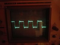
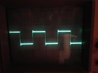
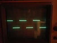
Square Wave, 20KHz to 500kHz
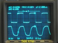
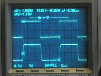
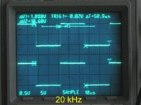
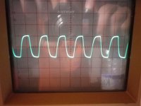
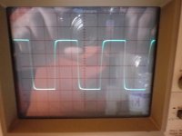
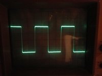
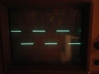
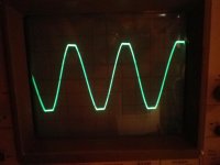
Next three pics show a square wave test, 20, 100 and 500kHz.
#4 - 20 kHz square wave, no attenuation or slew rate limiting seen
#5 - 100 kHz, rise and fall time can be seen, but still clearly a square wave
#6 - 500 kHz, practical limit for a square wave, distortion is obvious
Conclusion, clean square wave well above audio range.
Attachments
Last edited:
Slew Rate
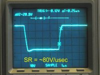
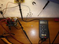
Next picture shows a rise time measurement with +/-30V supply, resulting in a maximum estimated slew rate of around 80V/usec. (A previous measurement under better test conditions and higher supply voltage showed around 100V/usec).
#7 - Slew rate, using rise time from 10% to 90% of Vp-p.
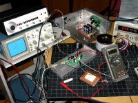
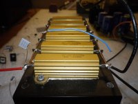
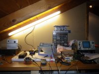
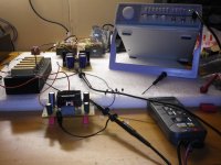
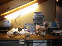
Final pic shows the test setup.
#8 - Tektronix PS280 bench supply @+/-30V, Wavetek 182A signal generator, Tektronix 2221A oscilloscope, Fluke 77 Multimeter. Tested w. resistive load only.
Next picture shows a rise time measurement with +/-30V supply, resulting in a maximum estimated slew rate of around 80V/usec. (A previous measurement under better test conditions and higher supply voltage showed around 100V/usec).
#7 - Slew rate, using rise time from 10% to 90% of Vp-p.
Final pic shows the test setup.
#8 - Tektronix PS280 bench supply @+/-30V, Wavetek 182A signal generator, Tektronix 2221A oscilloscope, Fluke 77 Multimeter. Tested w. resistive load only.
Attachments
Great and very precise work PMI, thanks for the measurements. 
I find a little difference with VSSA but not in a major scale, -3 dB point at 3 MHz (input filter & Zobel connected) and a little higher slew rate, around 150 V/us, but I am sure you'll extensively measure it by yourself later. Can you please also measure Zout and some RC loading, would be interesting too?
I find a little difference with VSSA but not in a major scale, -3 dB point at 3 MHz (input filter & Zobel connected) and a little higher slew rate, around 150 V/us, but I am sure you'll extensively measure it by yourself later. Can you please also measure Zout and some RC loading, would be interesting too?
Yes, although I cannot adjust the source (the Wavetek) accurately on the highest range (1-4MHz).Can you please also measure Zout and some RC loading, would be interesting too?
(Everything is manual, and just too sensitive, even to bumping the cart. I like the Wavetek, b/c it is all analog, but I never intended to be testing with it at those frequencies. For 1M and up I will need something else if we want accuracy.)
If you suggest a specific test or tests, and I will give it a shot.
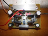
VSSA T03
2khz-2khz clip - 2khz -20khz-100khz-500khz
8Ω Load no zobel
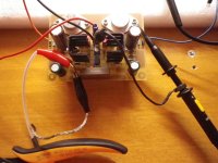
Mr Jason thanks for all and the board again .
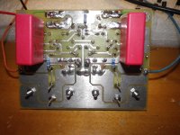
the litle noise solve look at pic 3 the green jumpers.
2khz-2khz clip - 2khz -20khz-100khz-500khz
8Ω Load no zobel
Mr Jason thanks for all and the board again .
the litle noise solve look at pic 3 the green jumpers.
Attachments
-
 IMGP1926.JPG400 KB · Views: 282
 -
 IMGP1924.JPG381.5 KB · Views: 292
 -
 IMGP1923.JPG315.9 KB · Views: 262
 -
 IMGP1922.JPG298.6 KB · Views: 231
 -
 IMGP1921.JPG328.5 KB · Views: 231
 -
 IMGP1920.JPG326.6 KB · Views: 330
 -
 IMGP1912.JPG499.7 KB · Views: 567
 -
 IMGP1907.JPG577.6 KB · Views: 568
 -
 IMGP1906.JPG471.8 KB · Views: 382
 -
 IMGP1905.JPG447.9 KB · Views: 528
Last edited:
VSSA T03
8Ω with 100nf no zobel
1khz-20khz-50khz
8Ω with 100nf no zobel
1khz-20khz-50khz
Attachments
Last edited:


- Home
- Amplifiers
- Solid State
- PeeCeeBee