Hi Shaan,
Peeceebee boards received today.
Much appreciated..
Thanks,
Boyet

")
Some time ago a diyaudio member(mindutis) donate me with theese boards.
He want to see these boards tested.
Now i must ask Shaan if this test can be posted here or a separate thread is necessary.
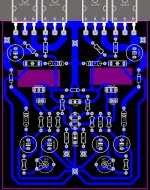
First thing that struck me, gate stoppers are so far away...shaan puts them very close I believe.
Otherwise looks very symmetrical.
Some time ago a diyaudio member(mindutis) donate me with theese boards.
He want to see these boards tested.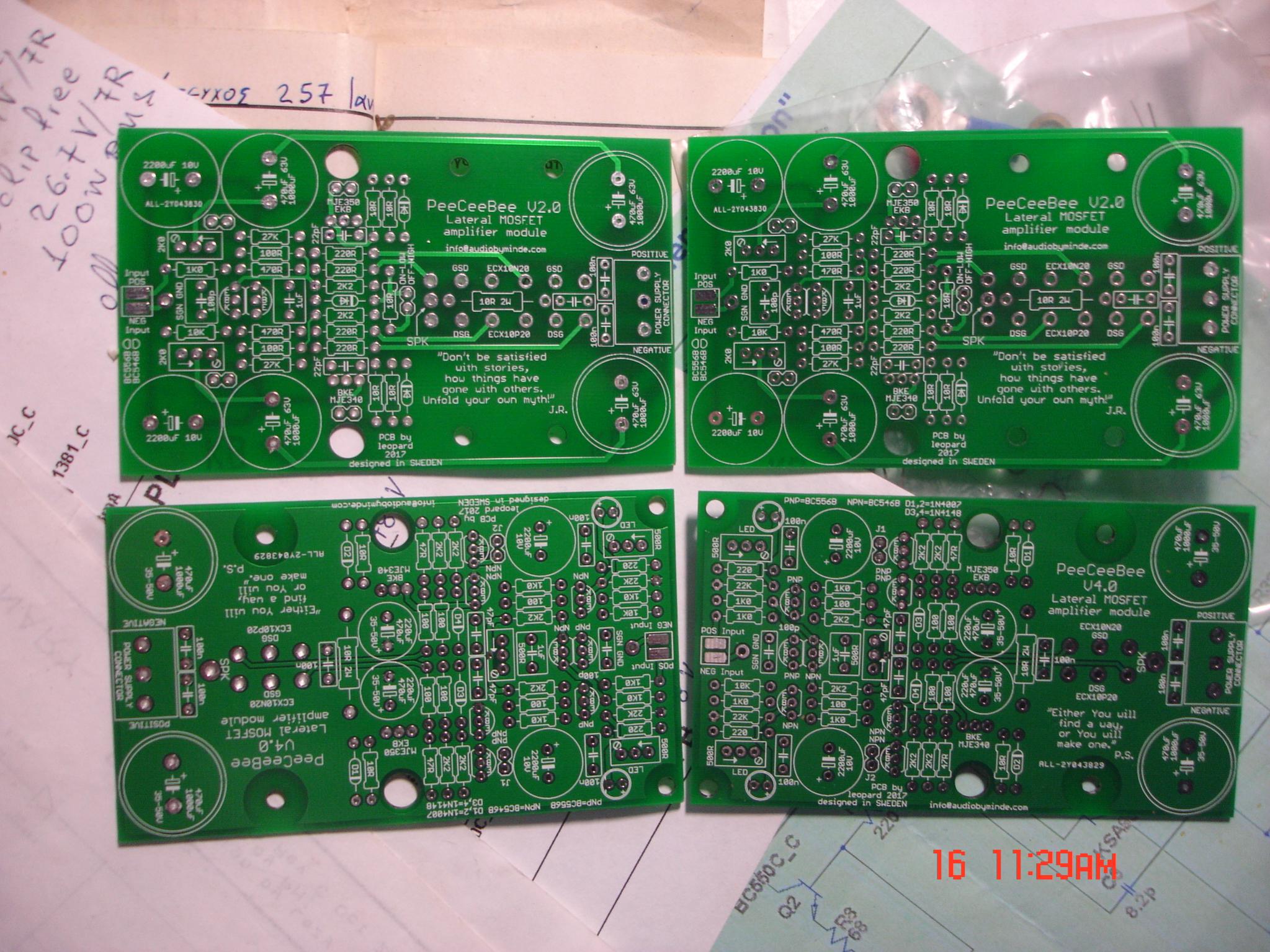
Now i must ask Shaan if this test can be posted here or a separate thread is necessary.
Hi Thimios.
Posting test results in this thread is most welcome after the full PDFs are uploaded for these boards.
Thanks.
shaan
Hi Shaan!
I hope this is the last question before I buy the remaining components, transistors and capacitors.
It is possible to supply V2 with only 35+35V DC? There are some variations in schematic?
How much will be idle current?
(I have a talema 25+25, when I can sell it, I will buy a big one)
I don't want to build first the V1.1 and second the V2. I want only ONE amp, so, the more power, the better!!
Thank you!!
Hi Franz.
Yes of course you can use 35v PSU for V2. Only things that need to be changed are the 27k resistors with 15k.
Bias current will be 50-70mA total. If you want to increase it then place a single turn 200R trimmer resistor in place of the 1n4148 (Remember to turn it to zero resistance probed between VAS collectors before powering up).
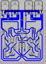
Well....what do you think about this horryble design?
I have made a mix of V1.1 and V2 and my own.
(I hope you are not angry for this mix.....)
I haven't inserted 10ohm and 100n in speaker output, they will be
inseted dierctly in bindig posts.
I have made a mix of V1.1 and V2 and my own.
(I hope you are not angry for this mix.....
)I haven't inserted 10ohm and 100n in speaker output, they will be
inseted dierctly in bindig posts.
Attachments
Last edited:
Hi Franz.
It's cool because this is what this thread is for - to make and share new PeeCeeBee layouts. So keep it up.
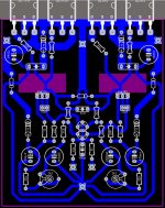
Try to put 100uF electrolytic caps as close as possible to the MOSFETs and also onboard zobel network may be unavoidable with this layout. Will wait for your tests on it.
It's cool because this is what this thread is for - to make and share new PeeCeeBee layouts. So keep it up.
Try to put 100uF electrolytic caps as close as possible to the MOSFETs and also onboard zobel network may be unavoidable with this layout. Will wait for your tests on it.
Hi Shaan,
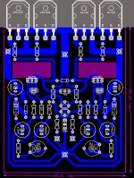
this is my limit....design a decent layout. I don't know where to move caps.
I will make a try...
MOSFETs are bloody fast and must have local rail decoupling capacitors from closest to drain leg to ground, or oscillation is almost certain.
Zobel will be in bindig posts...is wrong?
Might cause some discomfort to the MOSFETs, and might not. The inductance of the shared output trace can potentially cause parasitic oscillation in the MOSFETs at 10-40MHz frequencies and ruin your day. Better to have space for Zobel networks closest to the MOSFETs' source legs, then test if using them makes any difference. If not, omit them. The very first PeeCeeBee ran stably without Miller caps or Zobel. But it can't be expected nor guaranteed to be the same in every case.
As it will be a high power amp it's best to make sure it doesn't oscillate in standard operating conditions. All the bests.
Turn on the am/fm radio, tune it to a station and keep it close to the amp when it's on. If it's oscillating, the channels will be dead or extremely noisy.
Also monitor output offset, if it's too high like 5-10volts and cannot be trimmed to zero then most probably it's oscillating.
And there's a chance of high heat dissipation during oscillation so keep an eye on the heatsink temperature.
Also monitor output offset, if it's too high like 5-10volts and cannot be trimmed to zero then most probably it's oscillating.
And there's a chance of high heat dissipation during oscillation so keep an eye on the heatsink temperature.
Turn on the am/fm radio, tune it to a station and keep it close to the amp when it's on. If it's oscillating, the channels will be dead or extremely noisy.
Also monitor output offset, if it's too high like 5-10volts and cannot be trimmed to zero then most probably it's oscillating.
And there's a chance of high heat dissipation during oscillation so keep an eye on the heatsink temperature.

incredible!! ok, some days and i will made order for transistors and capacitors.
mmmmmhhhh.....
in the era of Peeceebee V4H....there is a little italian who tries V1.1
Hi,
When setting up the V4, would I be right in thinking that a 10R, 1/2W resistor in the supply rail(s) should work fine? If everything is ok, then total current draw should be about 110mA, so power dissipation on 10R resistor should be 0.12W, providing enough headroom even with a 1/2W resistor?
When setting up the V4, would I be right in thinking that a 10R, 1/2W resistor in the supply rail(s) should work fine? If everything is ok, then total current draw should be about 110mA, so power dissipation on 10R resistor should be 0.12W, providing enough headroom even with a 1/2W resistor?
- Home
- Amplifiers
- Solid State
- PeeCeeBee