A little bit of progress, I have to order the 2200uf caps.
Slow process....
Looks very nice. Wow you're using many varieties of capacitors!
")
Just a reminder: Before placing the transistors please read Post 397.
@asuslover
This is for VR1 and VR2 only. VR3 should be turned to zero resistance between leg 1 and 2 before powering up.
You can use 1K trimpot. Before soldering just turn them to measure 500-600 ohms between legs 1 and 2.
This is for VR1 and VR2 only. VR3 should be turned to zero resistance between leg 1 and 2 before powering up.
Yes, I had the caps already, the 47 of ceramic are now 51pf silver mica, the 100pf changed to 100pf /400v wima polypropylene and 3 of the 0.1uf film are now ceramic x7r/100v.I think it will be fine.And thanks for telling me about the 3rd trimpot, but I will read the info before to power it up.
Shaan, it looks like the drill template is not same size with the real pcb. I drilled today one and the distance between power transistors is 2mm smaller than needed.
In the first place i supposed the printer was wring but printed on another printer and cjecked all setiings to be "original" not fit to page or smthing else.
Can you check again please? The distance between the two drill holes for power transistors should be 71.5mm as measured with my pcbs.
I would like to drill a new set of holes asap as i'm very nervous to see how this amp sounds. I will use smps.
Thanks!
I used only pdf from your zip posted on my request some time ago
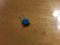
info about those:B32559C3104K000 EPCOS (TDK) | Capacitors | DigiKeyCool. But what are the two "open headed" 0.1uF near the MOSFETs? Never saw such capacitors before.
Maybe not the best cap here but I did not have any other ones.
Attachments
Shaan, it looks like the drill template is not same size with the real pcb. I drilled today one and the distance between power transistors is 2mm smaller than needed.
In the first place i supposed the printer was wring but printed on another printer and cjecked all setiings to be "original" not fit to page or smthing else.
Can you check again please? The distance between the two drill holes for power transistors should be 71.5mm as measured with my pcbs.
I would like to drill a new set of holes asap as i'm very nervous to see how this amp sounds. I will use smps.
Thanks!
I used only pdf from your zip posted on my request some time ago
That is strange because I have printed it a couple times and the dots perfectly match the holes! Well, my drilling instruments are not very "precise" so maybe it just didn't show up.
Anyways, I have made a fresh pdf from the drill file. Please try this and report. If it still shows the same effect then first mark the MOSFET drill holes, remove the paper and place a scale on both marks, align the scale correctly and make two new marks both at 1mm distance from the previous marks.
Attachments
info about those:B32559C3104K000 EPCOS (TDK) | Capacitors | DigiKey
Maybe not the best cap here but I did not have any other ones.
Nice. Wish these were available here. All Epcos I find are fully encased.
I don't know how to put a scale on a PDF. The PCBs are 91.5mmx63.5mm and I measured it to be exactly that. Now, I use qvPDF to print and the scaling is 100%. Maybe that little software is screwing the fun.
Here is another print directly from the Excellon file that I uploaded in the very first Zip in Post 211. Can you kindly check this please?
Here is another print directly from the Excellon file that I uploaded in the very first Zip in Post 211. Can you kindly check this please?
Attachments
Let me guess....
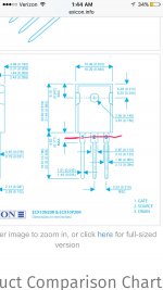
ECX10N20/ECX10P20 are a little bit different than the 2SK1058/2SJ162,
Atupi , are you trying to use the exc s mosfets?
How is the alignment for the pcb mounting holes?
I think you have to bend those legs all the way from the body of the transistors not from where the legs get skinnier, the wide part of the leg for an exicon transistor is longer than the wide part of the legs for the renesas transistors.
Plz correct me if I'm wrong...
Last edited:
Let me guess....
ECX10N20/ECX10P20 are a little bit different than the 2SK1058/2SJ162,
Atupi , are you trying to use the exc s mosfets?
How is the alignment for the pcb mounting holes?
I think you have to bend those legs all the way from the body of the transistors not from where the legs get skinnier, the wide part of the leg for an exicon transistor is longer than the wide part of the legs for the renesas transistors.
Plz correct me if I'm wrong...
Yes I think you are right as I am using the 2sk series and not the Exicons in mine. Now that should be the reason of mis-alignment I guess.
Yes i'm using Exicons but the misaligment is there not matter what trasistors you are using the pcb is not matchimg the pdf print regarding center of holes.
Maybe i'm missing something but i printed on 2 computers and 2 printers and the result is the same.
Yes asuslover, you need to bend the exicons legs very nasty.
Maybe i'm missing something but i printed on 2 computers and 2 printers and the result is the same.
Yes asuslover, you need to bend the exicons legs very nasty.
Yes i'm using Exicons but the misaligment is there not matter what trasistors you are using the pcb is not matchimg the pdf print regarding center of holes.
Maybe i'm missing something but i printed on 2 computers and 2 printers and the result is the same.
Hi Adrian.
I will upload a fresh PDF with 1mm more separation between the MOSFETs in the evening.
I wonder, you mentioned that even the overall board size to come out smaller in the print than the real PCB, not just holes printing closer. This looks like there may indeed be some problem during printing. But still, please wait till evening. I will make the aforementioned PDF as soon I get free.
Not only the distance between power transistors is wrong, everything is on a different scale. Printed 104% is close to real pcb.
I don''t have precision tools, only an old school non electronic caliper but i like to put the drill template on heatsink, puncture with a sharp nail the center of holes and after i make hole with 2.5 drill and after that create 3mm thread for screw.
I don''t have precision tools, only an old school non electronic caliper but i like to put the drill template on heatsink, puncture with a sharp nail the center of holes and after i make hole with 2.5 drill and after that create 3mm thread for screw.
- Home
- Group Buys
- PeeCeeBee V4 GB!