RCruz said:I meant I do have a pair of buffers, I built last year and did not power them up.... I was afraid to report that before I saw your comment
What type of output caps are you using ?
Ricardo
Hi Ricardo
I'm just using the parts supplied by Blair...Sonicap
I built my boards as soon as the parts arrived last year but they have gathering dust for the best part of a year.
I powered them up late last night but all I could hear was a nasty oscillation/hum. I am going to check the grounding again tonight...ah fun and games.
It seems I had a similar experience.
I have the buffers ready for several months now but never had the time to test.... (Been busy with salas riaa).
Please let us know what are your impressions regarding the sound !
I must convince myself to finally replace the opamp in my preamp.
Regards
Ricardo
I have the buffers ready for several months now but never had the time to test.... (Been busy with salas riaa).
Please let us know what are your impressions regarding the sound !
I must convince myself to finally replace the opamp in my preamp.
Regards
Ricardo
Hi there
I have been fiddling with this buffer for a couple of days and have decided add the low pass filter Blair omitted from his PCB design. The components have been thrown into a case for the time being, and I will probably place the buffers right next to the Chipamp boards if I am happy with the performance.
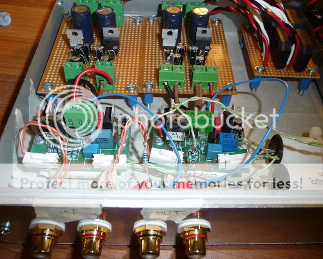
The low pass filter comprises of a 4.7uf sonicap, 47nf capacitor followed by a 75R resistor.
I have switched between using with and without the buffer and I cant really tell between the two. If I pull the power when the music is playing the sound cuts out, so it must be working to a degree!
The trimmers are set at 410R and the voltage across them is 2.48v (2.48/410=0.0060487mA)
Do you think I have done something wrong?
I have been fiddling with this buffer for a couple of days and have decided add the low pass filter Blair omitted from his PCB design. The components have been thrown into a case for the time being, and I will probably place the buffers right next to the Chipamp boards if I am happy with the performance.
The low pass filter comprises of a 4.7uf sonicap, 47nf capacitor followed by a 75R resistor.
I have switched between using with and without the buffer and I cant really tell between the two. If I pull the power when the music is playing the sound cuts out, so it must be working to a degree!
The trimmers are set at 410R and the voltage across them is 2.48v (2.48/410=0.0060487mA)
Do you think I have done something wrong?
Re: Wrong but Right
Thanks for clearing that up!
I understand the buffer should be transparent but surly I should be able to hear an improvement of sorts
I will have a good look at the circuit again tonight to see if there is anything wrong.
calvert73 said:The trimmers are set at 410R and the voltage across them is 2.48v (2.48/410=0.0060487mA)
Do you think I have done something wrong?
Well no its right but 2.48V/410R = 0.0060487A (not mA)
this is 6.0487mA Right!
RC
AndrewT said:Volts / Ohms gives Amperes.
Multiply Amperes by 1000 and you get mA.
Thanks for clearing that up!
I understand the buffer should be transparent but surly I should be able to hear an improvement of sorts
I will have a good look at the circuit again tonight to see if there is anything wrong.
I understand the buffer should be transparent but surly I should be able to hear an improvement of sorts
Richard, I have form time to time removed my buffer from the system and thought that it sounded better. A day or so later, and I notice something isn't quite 'right', the buffer goes back in and I prefer it with the buffer.
Often in this game it isn't a question of hearing something and appreciating what is happening straight away.
Re: Re: Wrong but Right
What are you comparing the buffer with ?
What is your present setup ?
Thank you very much for the precious feedback.... If you can not hear it, maybe it is very transparent... promissing.
Ricardo
Tripmaster said:
Thanks for clearing that up!
I understand the buffer should be transparent but surly I should be able to hear an improvement of sorts
I will have a good look at the circuit again tonight to see if there is anything wrong.
What are you comparing the buffer with ?
What is your present setup ?
Thank you very much for the precious feedback.... If you can not hear it, maybe it is very transparent... promissing.
Ricardo
Hi
I thought I would try biasing the buffer at 5.5mA (rather than 6mA) as Pedja recommends with this low pass filter combination.
'Considering a low pass filter, there are three options for R1: to omit it, to use lower value (75R) and to use higher value (1k). In the first case I could recommend usage of 47nF capacitor (C1). This will, with buffer biased at 5.5mA, give -3dB point at 90kHz, and -0.2dB roll-off (15° phase shift) at 20kHz. To go lower with roll-off slope, I’d rather recommend putting R1=75R in. The same 47nF then will give -1.4dB roll-off (and 35° phase shift) at 20kHz. Third option which can be used almost universally (regardless of the used buffer) assumes R1=1kOhm and with C1=4.7nF it will give -1.1dB, with C1=3.3nF -0.6dB and with C1=2.2nF -0.25dB attenuation at 20kHz. All previous numbers refer to the frequency response of the whole amplifier, numbers describing the filters themselves are slightly lower. Important numbers that refer only to the filters are those describing their own attenuation at 330kHz (about the HF behavior of the LM3875, refer to the mentioned Joe's articles) and for later three cases are respectively -19dB, -16dB and -12.5dB. In later case, if 1k is used for R1, with this buffer it is clear advance to put 33nF (C2) before R1 thus getting 2nd order filter. This 33nF doesn’t have influence on the amplitude response inside the audio band but attenuates further 7dB at 330kHz. Sonically, 33nF/1k/4.7nF filter compayellow with the 75 Ohm/47nF has even better soundstage but it is also somewhat mid-forward which may or may not be good, depending on the system synergy.'
Nick, can you remember what value you set your buffers at?
Richard
Re: Re: Re: Wrong but Right
Hi Ricardo
I'm using the buffers with a LM3886 dual mono amp, Pedja's discrete regulated power supplies, Shigaclone transport and a TDA1543 NOS DAC
RCruz said:
What are you comparing the buffer with ?
What is your present setup ?
Thank you very much for the precious feedback.... If you can not hear it, maybe it is very transparent... promissing.
Ricardo
Hi Ricardo
I'm using the buffers with a LM3886 dual mono amp, Pedja's discrete regulated power supplies, Shigaclone transport and a TDA1543 NOS DAC
Nuuk said:
Yes I can. Can you?
Hang on a second...let me just scroll up and read one of my previous posts
Nuuk said:
Yes I can. Can you?
Hi Nick
I guess you have the buffers set at 6mA
You mentioned in a previous post you have removed the buffer from time to time. Do you have your buffers hard wired to the LM3875s or are you running them from a separate case?
Nuuk said:Yes, 6mA for me. And the buffers are in a separate case so they can be used with other amps.
I also have another set of buffers that I am currently installing in the same case as a DAC.
Oh OK that’s interesting to know, thanks
- Status
- This old topic is closed. If you want to reopen this topic, contact a moderator using the "Report Post" button.
- Home
- Amplifiers
- Chip Amps
- Pedja Rogic Buffer and component choice for PCB design