Good morning Sirs ,
for some reason I have caps 30mm and not 25mm ... can I drill the board and offset the pin holes for the heatsinks ? I need to move the sinks back 2mm to get the Cap in .
Another question is about C15 .... what has been used there by others ?
Cheers , Rich
for some reason I have caps 30mm and not 25mm ... can I drill the board and offset the pin holes for the heatsinks ? I need to move the sinks back 2mm to get the Cap in .
Another question is about C15 .... what has been used there by others ?
Cheers , Rich
Last edited:
Got all my resistors welded in ... Caps on the way for the main board . Boards for the PSU .... touring the rockies ")
I got the variable caps for C9 ,but I having problems setting them . Excuse my silly question ,but am i right in thinking they can be set with a DMM providing it has a capacitance facility ? 5pf = .050 nf .. correct ? I can't get the meter read anything that small - I just put a new battery in too !
Any tips would be appreciated .
Thanks , Rich
5pf = .050 nf
5pF = 5/1000nF => 0.005nF
Oops, have I got the correct LED?
Hi guys,
Please keep in mind that I am new to this ...
I try to sketch what I am planning to build, because that way if I run into problems I do so before the actual building starts!
As I was sketching how I wanted to lay out my Pearl II into 3 boxes (1 for PSU and 1 for each channel) I realised I would also like an LED on the PSU box. As I have no idea what kind of voltages LED's can handle (I really am new to this but did realise 31V was probably a bit high!), I looked up what I had bought:
http://www.lumex.com/specs/SSL-LX5093VC.pdf
I now see that this particular LED requires 3.2V (4V max).
Is that OK for the LED that is supposed to go on the Pearl II boards?
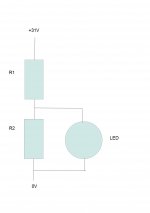
If I want to use this LED on the PSU box as well, I assume I should use a circuit like the attached jpg to bring the voltage down. Or can I leave out R2?
Now, to calculate R1 (and possible R2).
Do I assume that the resistance of the LED is 200 Ohm?
(I used V = 4 and I = 20mA from the datasheet to get R = V/I = 200)
Or should I measure it?
Your help is appreciated!
Thanks,
Albert
PS I also wanted to use these same LEDs for my F4's. Would they be OK or is it better to ask in the F4 thread?
Hi guys,
Please keep in mind that I am new to this ...
I try to sketch what I am planning to build, because that way if I run into problems I do so before the actual building starts!
As I was sketching how I wanted to lay out my Pearl II into 3 boxes (1 for PSU and 1 for each channel) I realised I would also like an LED on the PSU box. As I have no idea what kind of voltages LED's can handle (I really am new to this but did realise 31V was probably a bit high!), I looked up what I had bought:
http://www.lumex.com/specs/SSL-LX5093VC.pdf
I now see that this particular LED requires 3.2V (4V max).
Is that OK for the LED that is supposed to go on the Pearl II boards?
If I want to use this LED on the PSU box as well, I assume I should use a circuit like the attached jpg to bring the voltage down. Or can I leave out R2?
Now, to calculate R1 (and possible R2).
Do I assume that the resistance of the LED is 200 Ohm?
(I used V = 4 and I = 20mA from the datasheet to get R = V/I = 200)
Or should I measure it?
Your help is appreciated!
Thanks,
Albert
PS I also wanted to use these same LEDs for my F4's. Would they be OK or is it better to ask in the F4 thread?
Attachments
Hi guys,
Please keep in mind that I am new to this ...
I try to sketch what I am planning to build, because that way if I run into problems I do so before the actual building starts!
As I was sketching how I wanted to lay out my Pearl II into 3 boxes (1 for PSU and 1 for each channel) I realised I would also like an LED on the PSU box. As I have no idea what kind of voltages LED's can handle (I really am new to this but did realise 31V was probably a bit high!), I looked up what I had bought:
http://www.lumex.com/specs/SSL-LX5093VC.pdf
I now see that this particular LED requires 3.2V (4V max).
Is that OK for the LED that is supposed to go on the Pearl II boards?
If I want to use this LED on the PSU box as well, I assume I should use a circuit like the attached jpg to bring the voltage down. Or can I leave out R2?
Now, to calculate R1 (and possible R2).
Do I assume that the resistance of the LED is 200 Ohm?
(I used V = 4 and I = 20mA from the datasheet to get R = V/I = 200)
Or should I measure it?
Your help is appreciated!
Thanks,
Albert
PS I also wanted to use these same LEDs for my F4's. Would they be OK or is it better to ask in the F4 thread?
As this seems to be a high efficiency led, they get really bright and greedy at high Volts / Amps. You can turn them down a little by leaving out R2, and use trial and error value for R1. With 31V or so, you can try from 10k and go as high as about 68k2, depending how much light you want them to be lit
Eventually, if R value too high, it won't be lit, but with no other damage
Best,
nAr
Last edited:
As this seems to be a high efficiency led, they get really bright and greedy at high Volts / Amps. You can turn them down a little by leaving out R2, and use trial and error value for R1. With 31V or so, you can try from 10k and go as high as about 68k2, depending how much light you want them to be lit
Eventually, if R value too high, it won't be lit, but with no other damage
Best,
nAr
Thanks, nAr. I will start with 10k and see how I go. This will be in a few months time as we are still working on a pair of F4's and have a B1 to finish after that!
Universal Justice
Gents,
Excuse me for feeling rather smug ..... Pearl 2 fires up first time
Still all the tweaks to do . I used the 5pf silver mica caps at C9 .
I'm shocked and stunned ... FIRST TIME ! Anyway , back down to earth .
I need to get a better cartridge as I;m using an old DJ cartridge and the Veenil
I have is not the best production in the world.
Love the crackle and pop ..
There needs to be more gain , but there doesn't seem to be much point until I get a decent cartridge , a good test disk and everything has settled down .
I want to sit a read what others are up to before I touch it again , but I'm open to advice about things to try out .
Attachments
richluvsound,
Where's the power supply ground connected, the pad between the +pad and -pad?
+1
You must use symmetrical supply ;
GND 0V is halfway between V+ and V-;
otherwise won't work as intended
Best,
nAr
6L6,
But , But , But ................ ! Ok Dad
Seriously , I need a design for the PSU .
I have the boards . I have soldered the regs as per PD . LM317 + sinks on their way ....
I have Nichicon 10000 uf 50v Caps -2 per board
Can I take the B1 design you made for the B1 and double it ? Cap and resistor values ?
Rich
Don't use the 317's in the Peter Daniel board. Unfortunately, you should remove them from your board. The Pearl 2 has on-board regulation. It's the things with the heatsinks.
Here is the original supply design -
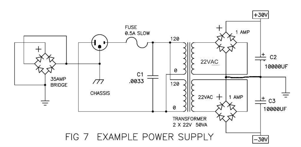
You also need to tie the two sides of the Peter Daniel board together.
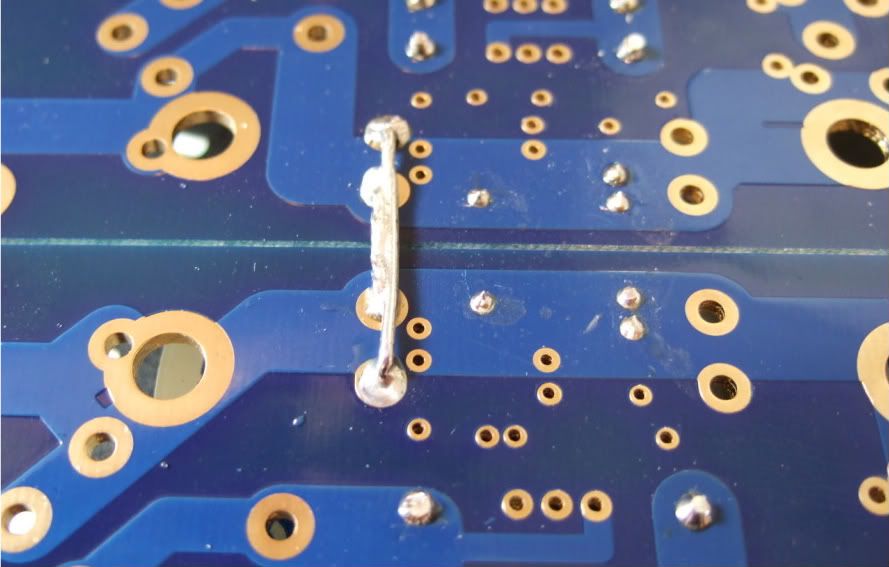
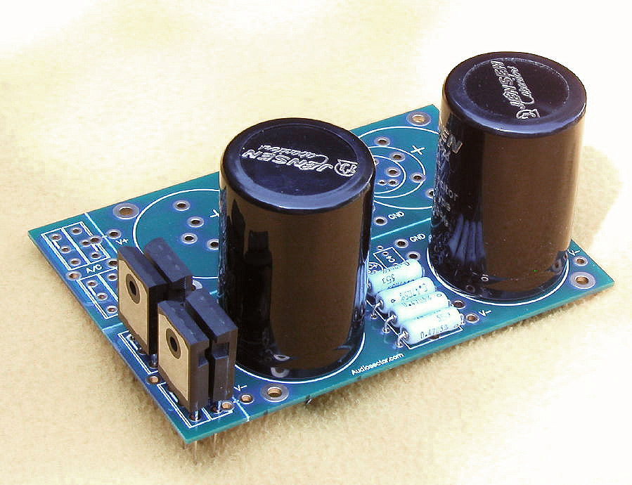
Once all the regulation is off the PSU board, you could put a couple of low-ohm (.5ohm, 1ohm, 2ohm...) resistors in, like this -
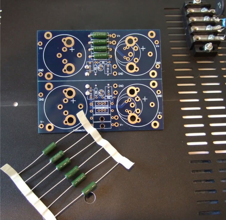
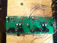
So once it's done, your board should be similar to this, (although both sided must be stuffed) here shown with the rectifiers still attached (assuming you are using discrete diodes)
Here is the original supply design -
You also need to tie the two sides of the Peter Daniel board together.
Once all the regulation is off the PSU board, you could put a couple of low-ohm (.5ohm, 1ohm, 2ohm...) resistors in, like this -
So once it's done, your board should be similar to this, (although both sided must be stuffed) here shown with the rectifiers still attached (assuming you are using discrete diodes)
Last edited:
Got a scare when I turned it off ...... Loud crack through the speakers .I need a full time carer .... that could have been 2 Berylium dia's up the bloody spout . There would have been tears before bed time .
So much I don't know about this stuff . I did art ,not physics . Physics was for getting high before art class
So much I don't know about this stuff . I did art ,not physics . Physics was for getting high before art class
- Home
- Amplifiers
- Pass Labs
- Pearl Two