Which positions are crucial, recommended or just simply good to have matched in this build? I'm interested in all tips, stand alone and between-the-channels, be it resistors, caps or fets.
My fets came from Pass labs together with boards. They are matched, but should I measure them and pair accordingly?
Avwerk on this thread recommended to:
"string each section together and tag each leg together with a little solder and measure each channel to make sure you have equal values for both boards, then insert caps."
Is it a "maniac party trick" or is it a way most of the builders went?
Do you have the most current voltage chart?
Here it is, if you don't have it --
http://www.diyaudio.com/forums/attachments/pass-labs/253484d1323200010-pearl-two-pearl2votages1.pdf
Please measure what you have and tell us what you read.")
Here it is, if you don't have it --
http://www.diyaudio.com/forums/attachments/pass-labs/253484d1323200010-pearl-two-pearl2votages1.pdf
Please measure what you have and tell us what you read.
Put 1R as interface in series at the Pearl nodes you attach the (+) & (-) reg wires for a test. Gives faster results in the presence of the 3300uF Pearl local caps at least, and it just may damp any bad interaction if present. Though you get 24V steady at the PSU feed nodes you say on the other hand.
Just to be clear I understood it correctly,
one leg of 1R would connect to (+) or (-) of the node connection and the second would go into boards (+) or (-) pads respectively. That would make 4 x 1Rs?
Just one at the central bridge feed node between channels will be enough. Two in total. On their other leg you solder whatever wiring goes to (+) & (-) now.
It's my first ever biasing (?) experience. When changing measuring range this morning I've got it to wandering 0.008V, whatever that means. I guess, it should be steady regardless the range and the voltages are still wrong. I'll try averaging mode in the evening and the "trick" Salas proposes. I can also present pictures if that helps.
Also, I have this arrangement before the shunts http://i46.tinypic.com/20qkrrm.png without direct ground return to the bridges that is.
Judging from the voltages I get, isn't the Q1 the most suspicious?
Also, I have this arrangement before the shunts http://i46.tinypic.com/20qkrrm.png without direct ground return to the bridges that is.
Judging from the voltages I get, isn't the Q1 the most suspicious?
Hello, again. I've tried relative mode on DMM. No help. I've connected ground direct to bridge ground like this:
http://i198.photobucket.com/albums/aa276/aeroplane_album/Pearl2PSU.jpg
didn't help either.
Here are some pictures:
http://i45.tinypic.com/29nz2iv.jpg
http://i48.tinypic.com/294gwsg.jpg
The grounds of L & R boards are tied together underneath with thick 0.6mm squared solidcore copper wire. Right in it's middle point respective ground and sense wires are connected from two shunts. Same goes for the "bridges" that you see above connecting to +/- pads and having +/- shunt Vout wires tapped right in the middle of them. I know, they don't remind the thing of beauty, but I was aiming for the shortest distance between pads for now. If you have suggestions how to make it proper, I'm all ears.
Here's a DC factory rat nest:
http://i46.tinypic.com/iqagyc.jpg
So, the voltages from the shunts seem stable, but I can't adjust P1 and having wrong measurements right below Q1.
Now I need your help. I can measure, make pictures and stay patient as much as a hard days night allows me.
You can't get proper biasing if you omit the voltage links on the boards. I assume you use shunt reg and no onboard regs. You need the 10R filtering resistors though, and also the big capacitors to be onboard. You also need to short in and out of the 78xx / 79xx holes onboard in order to get the voltages for proper biasing. Refer to 7824 and 7924 datasheet to find the good pinout
Best,
nAr
Best,
nAr
Last edited:
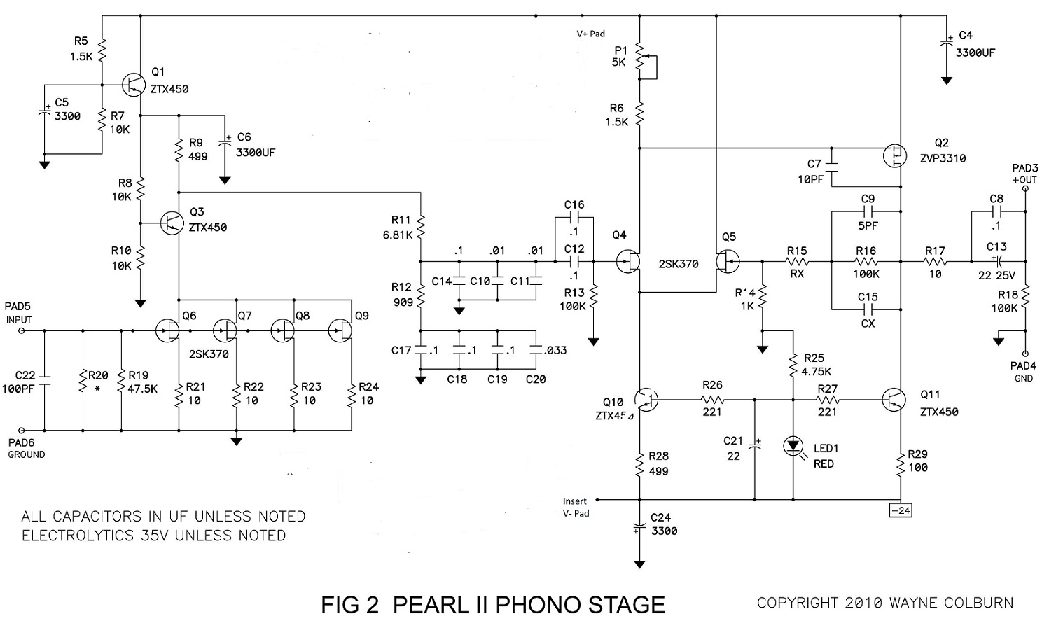
Anaël, yes I'm using shunts and this schematic, as proposed by Salas and tested by Tea-Bag already.
http://www.diyaudio.com/forums/gallery/data/1463/Pear_two_sans_regulator.jpg
Reading you now, I think, I've got my major mistake. I've bypassed the onboard regulators with a jumper from +DC IN pad to R4 point, BUT, I haven't bypassed or referenced ground. I wonder how the circuit worked at all!
http://www.diyaudio.com/forums/gallery/data/1463/Pear_two_sans_regulator.jpg
Reading you now, I think, I've got my major mistake. I've bypassed the onboard regulators with a jumper from +DC IN pad to R4 point, BUT, I haven't bypassed or referenced ground. I wonder how the circuit worked at all!
The bypass are under the board I guess ? Not easy to check at a first glance.
Do you have correct DC supply potentials in place on the Pearl boards ? It seems led is lit so it is a good sign. Maybe check with another multimeter ? Sometimes they can go wrong, had it when modding my Pearl II. Another meter worked fine
Best,
nAr
Do you have correct DC supply potentials in place on the Pearl boards ? It seems led is lit so it is a good sign. Maybe check with another multimeter ? Sometimes they can go wrong, had it when modding my Pearl II. Another meter worked fine
Best,
nAr
Last edited:
I have bypassed from +/- DC pads to respective points indicated on this schematic:
http://www.diyaudio.com/forums/gallery/data/1463/Pear_two_sans_regulator.jpg
The ground pads are just tied together. Should I have a link from them to somehwere? Yes, lids are lit.
When I check DC supply on Pearl boards I check on GND pad and the jump point.
http://www.diyaudio.com/forums/gallery/data/1463/Pear_two_sans_regulator.jpg
The ground pads are just tied together. Should I have a link from them to somehwere? Yes, lids are lit.
When I check DC supply on Pearl boards I check on GND pad and the jump point.
- Home
- Amplifiers
- Pass Labs
- Pearl Two