6L6,
I looked at that transformer because of the way I read this “This is by no means the only way to do it, so feel free to substitute any reasonable supply that delivers the required voltages (28 to 34 volts at 100 mA).”
Since I was not sure of it I asked the question to verify or correct what I interpreted. As you can tell I read it wrong. Better to ask first that buy it and be wrong then
Thank you for the links. As I stated when we spoke on the phone, the power supply part would take me a bit to get.
James
Luckily the PSU is actually quite easy, even more so with the chipamp.com PSU board. It is almost exactly the sample PSU shown by Wayne in the article. (drop the snubber and add one link and it's perfect.)
One trap that I think you might be falling into is that the DC voltage that you get after rectifying AC is higher (about 30-40% higher) than the AC voltage you start with.
The rule of thumb is to take the voltage you need (in our case just say 30v DC) and multiply by .7 to find the AC secondary voltage. (30 x .7 = 21) There are no 21v transformers, 22v is close enough, so use that. 24v secondaries would work as well.
LOL!! Sorry!! Try it now.
One trap that I think you might be falling into is that the DC voltage that you get after rectifying AC is higher (about 30-40% higher) than the AC voltage you start with.
The rule of thumb is to take the voltage you need (in our case just say 30v DC) and multiply by .7 to find the AC secondary voltage. (30 x .7 = 21) There are no 21v transformers, 22v is close enough, so use that. 24v secondaries would work as well.
Also is your link to the transformer really supposed to take me to a cap or was that a wrong link? Thanks.
LOL!! Sorry!! Try it now.
Last edited:
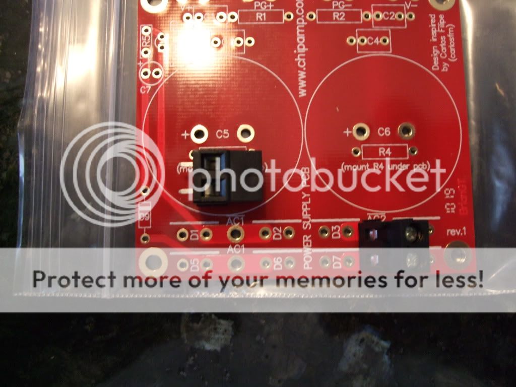
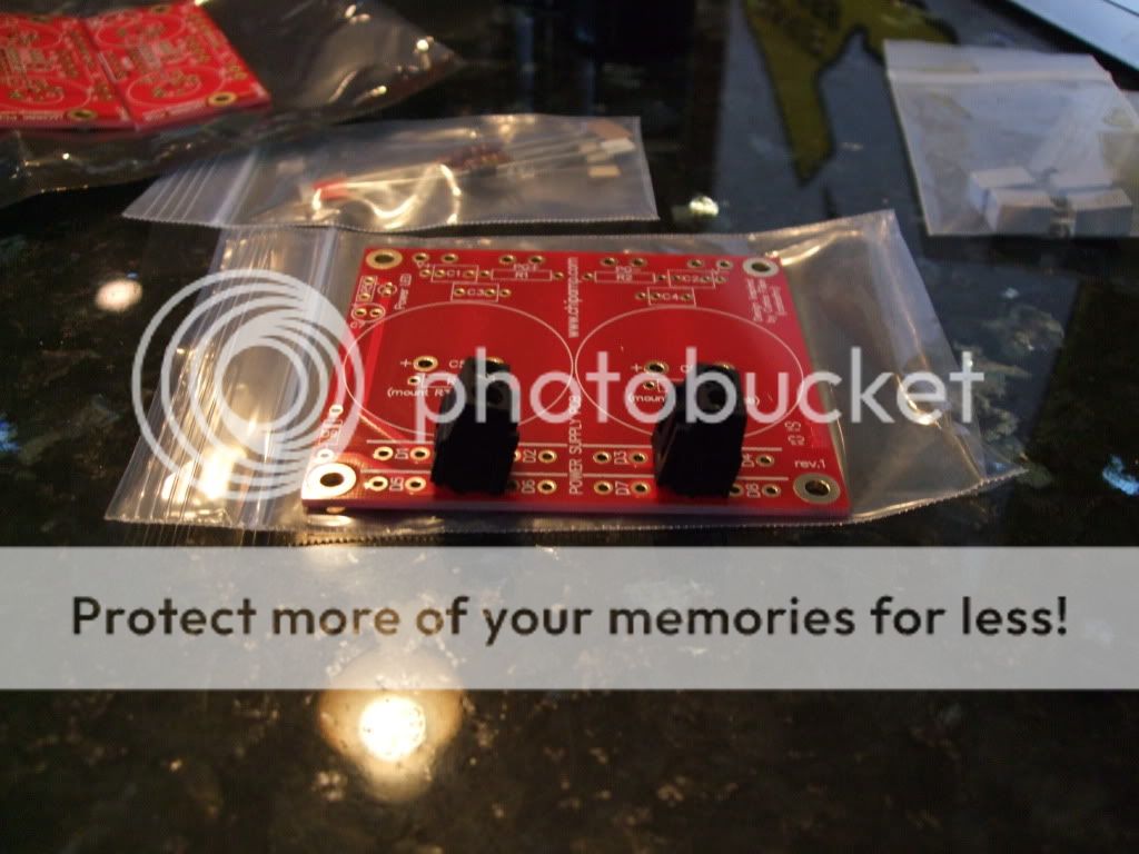
So I am about to start soldering the Chipamp board but just want to verify that these little devices should be soldered into AC1-AC2 section from underneath the board.
I also see on the board that R3-R4 should be solder from underneath the board. I have to assume this will keep those caps from sitting flush onto the board.
James
I also see on the board that R3-R4 should be solder from underneath the board. I have to assume this will keep those caps from sitting flush onto the board.
James
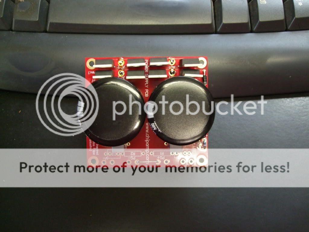
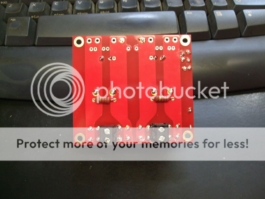
Well I was able to find a PDF for the power board which did state to attach the terminals beneath the board. So it is all soldered up at this time.
6L6,
If you happen to see this can you shot me a picture of that chassis we had spoken about? The VCR chassis I was going to use will not house everything.
Thanks.
James
6L6,
If you happen to see this can you shot me a picture of that chassis we had spoken about? The VCR chassis I was going to use will not house everything.
Thanks.
James
A good PCB makes anything easier -- even the things that can be done point-to-point.
Power supply kit ordered!
Russellc
Russell,
If you ordered the same unit as I did the PS-KIT, it does not come with any documents or anything.
I was able to find this on line for it though. What I found funny about that is it is from their website but if you go out there, there is no "docs" link, at least that I could see (could have just flat out missed it though).
http://chipamp.com/docs/lm3886-manual.pdf
James
Russell,
If you ordered the same unit as I did the PS-KIT, it does not come with any documents or anything.
I was able to find this on line for it though. What I found funny about that is it is from their website but if you go out there, there is no "docs" link, at least that I could see (could have just flat out missed it though).
http://chipamp.com/docs/lm3886-manual.pdf
James
Thanks....Yes I swear they used to have the Aleph boards schematics, but I cant find it now.
Russellc
Here are some photos of a battery powered Pearl 2 and a B1 build. I have to say that these sound, well, phenomenal! After years of trying different electronic equipment searching for that sound that you can say, "this is it", Yes, I can say "this is it!" One can sit, hear, and listen to the music with awe. There is such a quietness and presence that the music is almost in a way unbelievable at times. I also have a AKSA 100 N+ amplifier and Statement monitors. As for the sound of digital, well, it is exactly that.
I would like to thank Wayne Colburn and Nelson Pass for the designs and input. 6L6 (Jim) for his help and for the grounding and voltage checks. And Curt from Speaker Design Works for directing me to the B1 and Pearl 2 and the charger input and guidance through the builds along with multiple excellent speaker builds.
Here are some photos, enjoy!
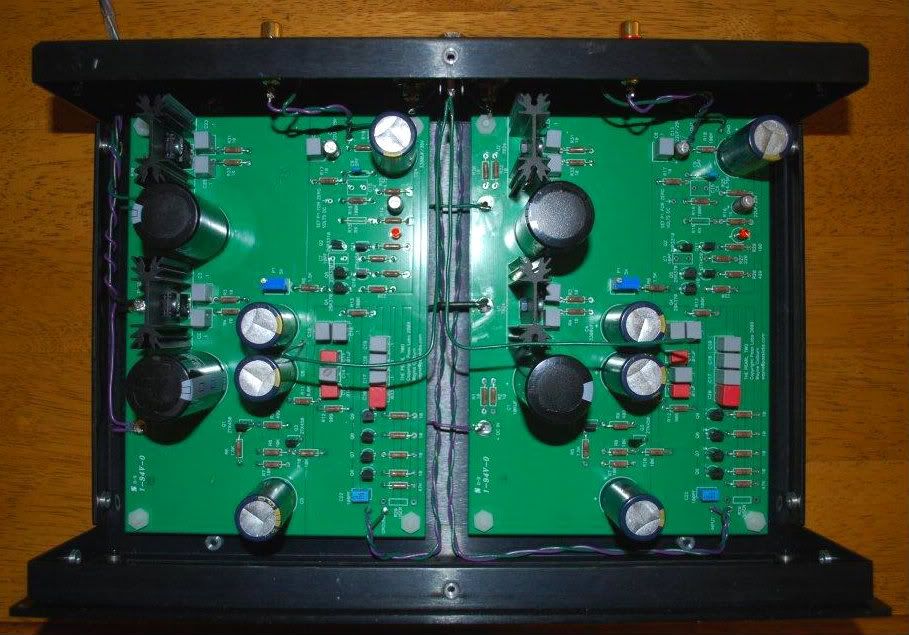
Pearl 2, inside the RIAA box
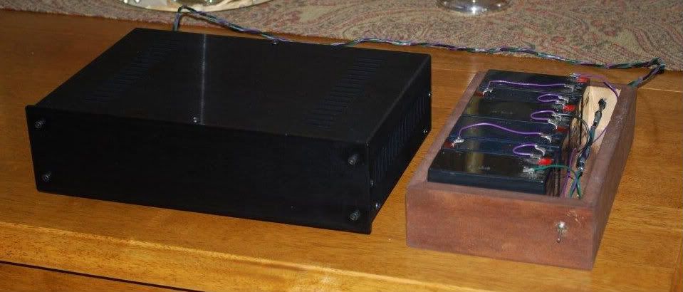
Sealed lead acid battery PSU and Pearl 2
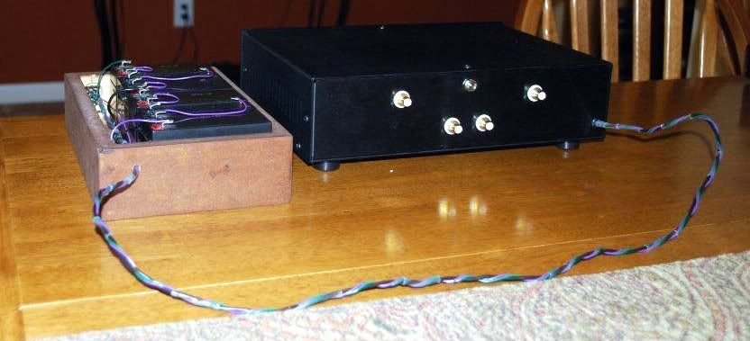
From the back
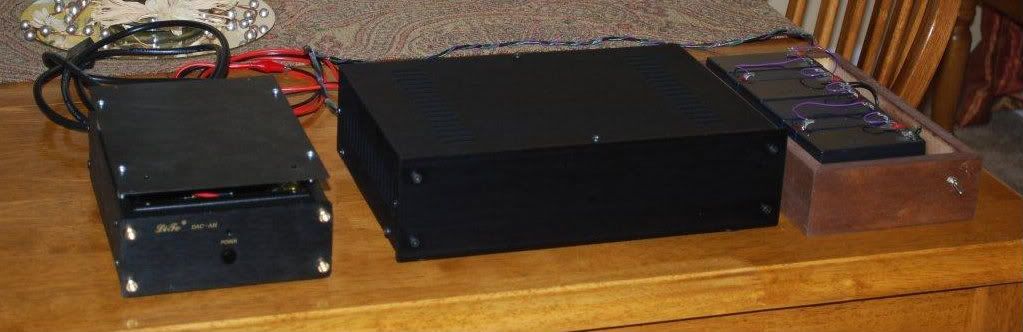
Shown with charger
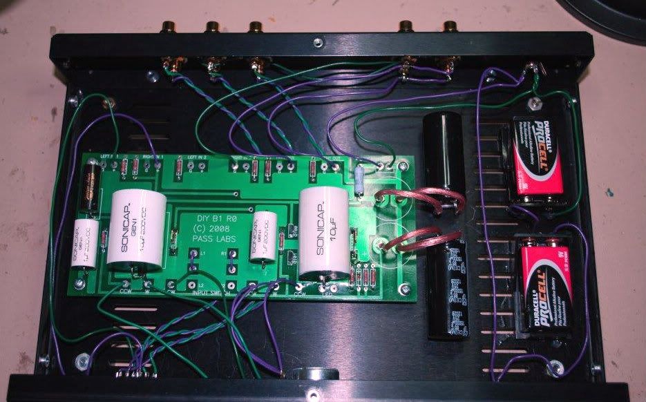
And here are the insides of the battery powered B1.
I would like to thank Wayne Colburn and Nelson Pass for the designs and input. 6L6 (Jim) for his help and for the grounding and voltage checks. And Curt from Speaker Design Works for directing me to the B1 and Pearl 2 and the charger input and guidance through the builds along with multiple excellent speaker builds.
Here are some photos, enjoy!
Pearl 2, inside the RIAA box
Sealed lead acid battery PSU and Pearl 2
From the back
Shown with charger
And here are the insides of the battery powered B1.
See my own built at http://www.diyaudio.com/forums/pass-labs/212050-my-pearl2-built.html#post3010966
So I have either picked up or order what I believe to be the last small parts.
regulator
fuse holder
fuses
Cap for power supply
red leds
I also have on hand some Arctic Silver 5, will this work for the IC’s and heat sinks?
Next things to do is get some small nuts and bolts for the heat sinks. Also need to place everything on paper to see if it will fit for a chassis I am looking at.
What size standoff are people using beneath the boards? Is everyone also using nylon washers on each side of the boards where the standoffs go?
Slowly making it there.
James
Hopefully that't the last of the little bits you need for the project!
A couple of nylon washers underneath the board makes a nice standoff, sometimes even nicer than 'real' standoffs. I use 4-40 hardware to mount PCB's, RadioShack has a nice bag with lots of good sizes for cheap. Also, you might be able to find some nylon spacers at your local hardware store.
Arctic silver is an adhesive, (unless I am mistaken) so I wouldn't glue the regulators to the heatsinks. If your regulators are the encapsulated TO-220 (with the plastic back) then just a little heatsink compound (the white stuff) will be fine. If they are metal-backed, you will need an insulator and shoulder washers.
6L6,
The Artic Silver 5 is a Thermal Compound (Polysynthetic Silver – High Density). Still no good?
I also misspoke; it was the Bridge Rectifier I ordered (not a regulator). The one below is what I got.
http://www.mouser.com/ProductDetail...=AvlKB63p5SmIIYUfX9PFbbdMlX/AHSf73z4BWuZQpu8=
Thanks, James
The Artic Silver 5 is a Thermal Compound (Polysynthetic Silver – High Density). Still no good?
I also misspoke; it was the Bridge Rectifier I ordered (not a regulator). The one below is what I got.
http://www.mouser.com/ProductDetail...=AvlKB63p5SmIIYUfX9PFbbdMlX/AHSf73z4BWuZQpu8=
Thanks, James
Last edited:
- Home
- Amplifiers
- Pass Labs
- Pearl Two