So you did it ? Well, now time to cheer then
Happy New Year 012,
nAr
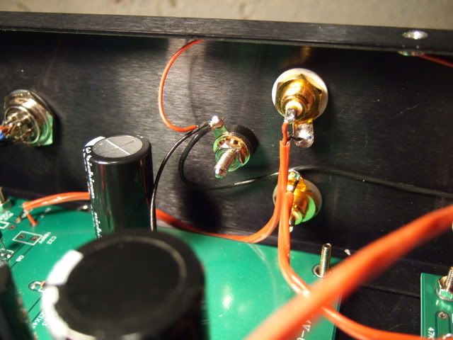
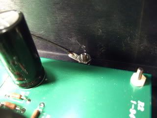
Nah ! crap . Getting the board to measure OK is one thing, but getting something other than some sort of static out of it is something else .
I have one perfect channel and one junk . I need to get hold of another TT to try also .
I keep having to adjust P1 . Can't see the wood for the trees at the moment.
I need to get some help , or put it away . Feeling beaten is not how I want the year to start .
Rich .
Has anyone tried changing the value of C22, or removing it completely? I generally try to keep capacitance as low as possible for a brighter sound.
Mark
The first Pearl did not have C22. So although I have not done so myself, I would assume that it is safe to remove it.
The first Pearl did not have C22. So although I have not done so myself, I would assume that it is safe to remove it.
True
")
MacQuaide, I thought that the loading value would add some capacitance at the input, it adds itself to the cable from cart stray capacitance ... right ? I also believed that the more capacitance value added, the birghter the sound. Maybe I'm totally wrong here, I thought removing the cap would lead to a less brighter sound ( less treble compensation )
Best,
nAr
True
MacQuaide, I thought that the loading value would add some capacitance at the input, it adds itself to the cable from cart stray capacitance ... right ? I also believed that the more capacitance value added, the birghter the sound. Maybe I'm totally wrong here, I thought removing the cap would lead to a less brighter sound ( less treble compensation )
Best,
nAr
Hi nAr, moving magnet cartridge loading can be complex. There is an interplay between capacitive and resistive loading. Generally you try to use a low capacitance interconnect between the turntable and phono preamp. Then capacitance can be added or removed at the preamp.
I believe that once capacitance from the tonearm through to the preamp gets too high (say over 300pf) it starts to "dull" the sound. Some say to reduce the capacitance as much as possible, then tune the resistance for flat response.
Moving coil carts are not sensitive to capacitance but resistance needs to be much lower (say 100-200 ohms as opposed to 47,000).
I'm sure there are others here with a much better grasp of the mathematics!
Mark
Subjective impressions needed. My brother has a Conrad Johnson Tube Phono Stage and I wanted to build this for him. How will it match up?
Jfets will never sound like tubes. they are more of the "pentode" style sound, very crisp, natural and detailed. Tubes often have a more round, triode typical character. So far what I can say is that I really enjoy the Pearl II. It is hooked to UGS with Aleph_J power amps. This seems very coherent sounding. I'm gonna soon upgrade the psu/regulation of the Pearl in dual mono, to see which are his limits.
Best,
nAr
Thanks !
Hey,
I'm not giving up . I had hoped to have it finished and working by now ,but no luck . Please don't think the kindness and support has been dismissed - I'm very ,very grateful to all .
I have an exhibition to get ready for and limited space in which to work .
Besides , can you imagine trying to remove oil paint from vinyl
I'll keep reading and watching . It bugs the crap out of me though . I had one side working perfectly ... no hum either . I disconnected it to check the new cable installed from the TT plugged it back in and SFA came out of either side .
I have a couple of friends that may be able to help hands on , I have been working so hard at it ,that now,its just become a painful , expensive blur :/
Rich
An update to my project - I have had a lot of progress, actually a couple of weeks ago, and have not had the time to post!
As I mentioned a some time ago, my rectified voltage was about +/- 47v .
The original 10ohm resistors in the CRCRC filter were obviously not enough resistance to reduce the voltage, so I reached into my somewhat meager supply of high-wattage resistors and kludged up this -
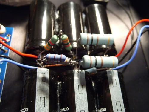
Now the eagle-eyed of you will notice that they are not symmetrical... and that is because the (+) rail draws more current than the (-) And all I was trying to do was get the voltage at the input of the regulators somewhere between 40 and 29. Fewer than 40v as that is the maximum the 7*24 regulators can have on the input, and at least 29 because the regulators need at least 5v more than the output in order to regulate properly. They are now about 31v.
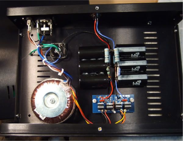
Here is the entire power supply, the power entry module has a switch and fuse, you can see the 35amp bridge isolating the PSU ground from the safety earth, the toroid, rectifier board with snubber and LED, then the CRCRC filter.
The output from the PSU, positive, negative and ground are isolated from the chassis. The umbilical is just a 3-conductor cable.
Just for reference, here is a photo of the backs of the enclosures -
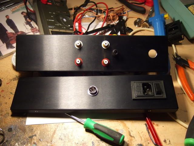
I mentioned that the guy that I had do some machining for me screwed up the RIAA enclosure and did it upside-down. In the grand scheme of things this is not a big deal, but it did mess up my wiring, specifically where the power cable got routed.
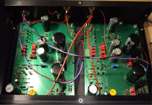
Now this rat's nest is not the final wiring, but it is quiet. Very quiet. I will get around to a nicer looking routing in the near future.
The grounding is as mentioned in an earlier post - everything is floating on the chassis, the starground from the board is connected to the ground lug.
And then the lug is connected to the chassis, I just used a longer screw in the pem nut, a tab and a metal nut to insure good conductivity.
Like I mentioned earlier, it is quiet and sounds fantastic. I will take a few more photos and make a 'start to finish' thread once I re-do the wiring.
As I mentioned a some time ago, my rectified voltage was about +/- 47v .
The original 10ohm resistors in the CRCRC filter were obviously not enough resistance to reduce the voltage, so I reached into my somewhat meager supply of high-wattage resistors and kludged up this -
Now the eagle-eyed of you will notice that they are not symmetrical... and that is because the (+) rail draws more current than the (-) And all I was trying to do was get the voltage at the input of the regulators somewhere between 40 and 29. Fewer than 40v as that is the maximum the 7*24 regulators can have on the input, and at least 29 because the regulators need at least 5v more than the output in order to regulate properly. They are now about 31v.
Here is the entire power supply, the power entry module has a switch and fuse, you can see the 35amp bridge isolating the PSU ground from the safety earth, the toroid, rectifier board with snubber and LED, then the CRCRC filter.
The output from the PSU, positive, negative and ground are isolated from the chassis. The umbilical is just a 3-conductor cable.
Just for reference, here is a photo of the backs of the enclosures -
I mentioned that the guy that I had do some machining for me screwed up the RIAA enclosure and did it upside-down.
In the grand scheme of things this is not a big deal, but it did mess up my wiring, specifically where the power cable got routed.
Now this rat's nest is not the final wiring, but it is quiet. Very quiet. I will get around to a nicer looking routing in the near future.
The grounding is as mentioned in an earlier post - everything is floating on the chassis, the starground from the board is connected to the ground lug.
And then the lug is connected to the chassis, I just used a longer screw in the pem nut, a tab and a metal nut to insure good conductivity.
Like I mentioned earlier, it is quiet and sounds fantastic. I will take a few more photos and make a 'start to finish' thread once I re-do the wiring.
Last edited:
An update to my project - I have had a lot of progress, actually a couple of weeks ago, and have not had the time to post!
As I mentioned a some time ago, my rectified voltage was about +/- 47v .
The original 10ohm resistors in the CRCRC filter were obviously not enough resistance to reduce the voltage, so I reached into my somewhat meager supply of high-wattage resistors and kludged up this -
Now the eagle-eyed of you will notice that they are not symmetrical... and that is because the (+) rail draws more current than the (-) And all I was trying to do was get the voltage at the input of the regulators somewhere between 40 and 29. Fewer than 40v as that is the maximum the 7*24 regulators can have on the input, and at least 29 because the regulators need at least 5v more than the output in order to regulate properly. They are now about 31v.
Here is the entire power supply, the power entry module has a switch and fuse, you can see the 35amp bridge isolating the PSU ground from the safety earth, the toroid, rectifier board with snubber and LED, then the CRCRC filter.
The output from the PSU, positive, negative and ground are isolated from the chassis. The umbilical is just a 3-conductor cable.
Just for reference, here is a photo of the backs of the enclosures -
I mentioned that the guy that I had do some machining for me screwed up the RIAA enclosure and did it upside-down.
Now this rat's nest is not the final wiring, but it is quiet. Very quiet. I will get around to a nicer looking routing in the near future.
The grounding is as mentioned in an earlier post - everything is floating on the chassis, the starground from the board is connected to the ground lug.
And then the lug is connected to the chassis, I just used a longer screw in the pem nut, a tab and a metal nut to insure good conductivity.
Like I mentioned earlier, it is quiet and sounds fantastic. I will take a few more photos and make a 'start to finish' thread once I re-do the wiring.
Great! Your start to finishes are the bomb, and this one is very timely as I need to build my Pearl 2!!!
Russellc
Today I had a little bit of time to make the wiring a bit neater. The signal wiring is done, it looks much better. The PSU has to wait to tomorrow, I ran out of time. (My workspace is accessed through the nursery, and my two year old needed to go to bed.)
The PSU wiring will only take a few minutes to change, photos when it's complete.
A bit of surprise, the neater wiring is quieter! It was plenty quiet before, but having it be better is very welcome. It's probably because all the wires are routed near the chassis.
The PSU wiring will only take a few minutes to change, photos when it's complete.
A bit of surprise, the neater wiring is quieter! It was plenty quiet before, but having it be better is very welcome. It's probably because all the wires are routed near the chassis.
Ok... Photos!
This build is complete, it sounds fantastic and is really quiet. I'm very, very happy with the results.
Now I need to sell off some of my random excess gear and buy a Shelter 501 cartridge...
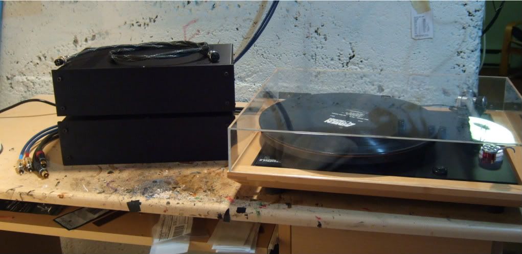
The completed Pearl 2. Shown with Turntable for scale.
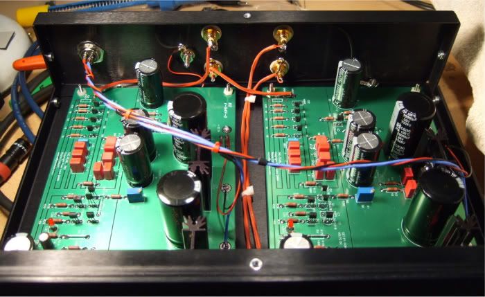
Wiring after the clean-up. It looks better and is quieter. Awesome!!
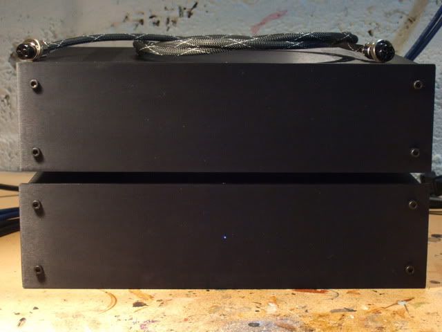
The stealth blue power indicator. On top is the umbilical.
That's it for my build in this thread. I am working on the start to finish thread right now, will post it when it's done.
Gentlemen, thanks so much for your support in this endeavor, I am truly grateful!
This build is complete, it sounds fantastic and is really quiet. I'm very, very happy with the results.
Now I need to sell off some of my random excess gear and buy a Shelter 501 cartridge...
The completed Pearl 2. Shown with Turntable for scale.
Wiring after the clean-up. It looks better and is quieter. Awesome!!
The stealth blue power indicator.
On top is the umbilical. That's it for my build in this thread. I am working on the start to finish thread right now, will post it when it's done.
Gentlemen, thanks so much for your support in this endeavor, I am truly grateful!
Thank you! It's been a blast to build.
How are you enjoying yours now that it quiet?
EDIT ---
And here is the "Start to Finish" thread on my build. Enjoy! http://www.diyaudio.com/forums/pass-labs/204336-building-pearl-2-a.html
How are you enjoying yours now that it quiet?
EDIT ---
And here is the "Start to Finish" thread on my build. Enjoy! http://www.diyaudio.com/forums/pass-labs/204336-building-pearl-2-a.html
Last edited:
Thank you! It's been a blast to build.
How are you enjoying yours now that it quiet?
I'm thrilled with it. I had a listening session at my home recently, and suffice it to say that some of the folks are looking to upgrade their phono preamps after hearing it!
Mark
Hello,
I'm considering this project and have a couple questions. Does this stage "color" the input? Is the stereo field affected, modified? Would you guys consider this a "pro" level phono stage or should I look else where? Lastly, what level of construction would you guys consider the build (easy, normal, hard)?
-Thanks
fabricio - It sounds fantastic, it does not color the input. The stereo imaging is very, very good. It is a fantastic phono stage with few peers. I would happily listen to it compared to any other phono stage in the world.
Construction difficulty is always hard to gauge, as it has much to do with your skill. However, if you are going to order all the components new, there is a circuit board for all the parts of it, which greatly simplifies things.
If you haven't seen this thread yet, you should look at this - http://www.diyaudio.com/forums/pass-labs/204336-building-pearl-2-a.html
- Home
- Amplifiers
- Pass Labs
- Pearl Two