Does anyone have a Digikey part No for the zvp3310 I need ...
This is the TO-92 package - Digi-Key - ZVP3310A-ND (Manufacturer - ZVP3310A)
")
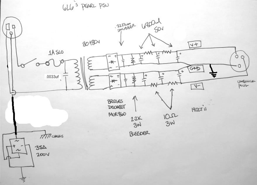
I had the honor of talking to Wayne himself yesterday, and he verified that a CRCRC filter for the psu would be a fine way to get rid of my extra voltage. The goal is to get the rectified 42 volts down to 34, to keep the on-board caps and regulators happy. Luckily, the 7824/7924 regulators are happy with up to 40v, but the specified caps are only 35v.
At this point I have made an order for all the necessary components to stuff the boards, and need to look at my inventory of connectors and jacks for the chassis. Speaking of chassis, the plan is a Par-metal for the audio circuit, but I'n not sure if I am going to make an identical chassis for the psu, or use a suitable box that I have in my parts bin that would be appropriate. (I will prototype it in that box for sure...)
Talking to Nelson and Wayne both at Burning Amp, it was interesting to understand just how much they know that having the PSU separate from the circuit makes a positive impact on the performance. Not really that surprising in a phonostage, but Nelson even suggested that I build my Jfet/Jfet Aleph power amp with a separate PSU. That's actually quite interesting when you think about it.
Cool , a build buddy !
heat-sinks ? Digikey ? I'm trying to boost my order so I get free shipping .
Also , I need DC plug for the PSU to the Pre . Whats the tekky name name for them ?
Rich
I'm in process to bypass the onboard 78XX / 79XX and add external UGS_PSU ( 24V reg) + adapting that PSU to 30V for my AlephOno ... as an upgrade ...
nAr
Rich -
do you have a schematic or link to Brians universal board? I'm not sure what they are. BUT, with a name like 'universal' they will probably be great, as the PSU is very simple.
As for DC transmission, you could make an umbilical from an XLR plug... I use things called 'microphone connectors' at Radioshack, and I have some really overkill, sealed, military-spec 6-pin connectors that would work quite well.
The heatsinks are for TO-220 package, something like this - - Digi-Key - 294-1024-ND (Manufacturer - 7-338-1PP-BA)
there may be cheaper options, I only looked for an example.
Nar -
Please do post your construction and impressions of the modified PSU, I am very interested in your results! As this will be 2-chassis, it will be very easy to implement.
http://www.diyaudio.com/forums/audio-sector/149672-universal-power-supply-pcb.html
I'm hoping to build the B1 PSU at the same time .
I tried getting the missing values from Micheal percy ,but they only have .5 watt ... I'll try in the UK :
221k , 909 R , 47.5k and 499 R .25 watt still needed .
Rich
I'm hoping to build the B1 PSU at the same time .
I tried getting the missing values from Micheal percy ,but they only have .5 watt ... I'll try in the UK :
221k , 909 R , 47.5k and 499 R .25 watt still needed .
Rich
Oh - Peter's universal board. Yep, wonderful, totally appropriate (and somewhat overkill...perfect!) for the pearl. Get (8) MUR860 diodes for this. Actually, (12) because you need 4 for the B1.
Only 1/2 watt resistors available instead of 1/4? Get them from Percy and use them. Dissipation only matters when it is to small.
Only 1/2 watt resistors available instead of 1/4? Get them from Percy and use them. Dissipation only matters when it is to small.
6L6 , when someone refers to "Brians" boards , i believe they are referring to this brian Chipamp.com
he also sells aleph pcbs and aleph ps pcb's
cheers Woody
he also sells aleph pcbs and aleph ps pcb's
cheers Woody
6L6 , when someone refers to "Brians" boards , i believe they are referring to this brian Chipamp.com
Yes, that's what I thought as well, but he really doesn't have a 'universal' PSU board.
These are the Diodes - Digi-Key - MUR860GOS-ND (Manufacturer - MUR860G)
That board was made with them in mind.
I have my Pearl boards and am going to use a (because I have it on-hand) Peter Daniel chipamp PSU board (which basically will only hold the diodes and one small snubber cap) and either use perfboard or just Point-to-Point the 'big' caps and the resistors.
That board was made with them in mind.
I have my Pearl boards and am going to use a (because I have it on-hand) Peter Daniel chipamp PSU board (which basically will only hold the diodes and one small snubber cap) and either use perfboard or just Point-to-Point the 'big' caps and the resistors.
Rich,
Remember that my PSU has the requirement of dropping a few volts, because the transformer I'm using is a higher voltage than specified.
Anyway, Wayne figured that most people would just buy another pair of the 10000uf 35v electrolytic caps -- the same that are on the PCB. However, if you are using the Peter Daniels universal board, (which has room for 4 caps) I would buy a quad of them, or something similar. It mainly depends on your box for the PSU.
Morning ,
I guess my values wont change . Boards shipped today from Peter ( nice guy for a Canuck )
Should I add these parts to my digikey order ?
BTW I'm using these Digi-Key - 1003-1192-ND (Manufacturer - 127010-0030)
The 35 amp 200v rectifier is confusing me ?
also ... R15 = RX please explain ?
Caps http://search.digikey.com/uk/en/products/UVR1H103MRD/493-1119-ND/588860 OK ?
Have a great day all !
Last edited:
Rich -
The plugs you picked out will work, but 6 pin just makes it harder to solder and work with. You only need 3 pins.
The big bridge is a ground loop breaker. Signal ground connects to it, and then the chassis through the diodes, to keep the signal off the metal chassis. The diodes have to be really big in case there is an actual earthing problem, to pass the possible current.
R15 is normally a jumper. Here is Wayne from the manual;
"The overall gain of the circuit as shown is 55 dB @ 1K Hz. Decreasing R14 from 1K to 300 Ohms gives 10 dB more gain when desired for lower output cartridges. R15 which normally would be shorted to 0 ohms can be replaced by a resistor to provide more gain as an alternative to reducing the value of R14. C15 has been placed on the board to allow for additional adjustment of equalization. In both cases these values are up to you."
- Home
- Amplifiers
- Pass Labs
- Pearl Two