I already put the PCB design in the thread `Bridgle or Parallel" where I had put the circuit design sometime back. But as I need suggestions and corrections for the circuit and the pcb design, I thought I should start a new thread with a different title.
The links are:
Cirsuit. http://www.diyaudio.com/forums/attachment.php?s=&postid=529675&stamp=1102598305
Power Supply.
http://www.diyaudio.com/forums/attachment.php?s=&postid=537485&stamp=1103622043
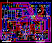
A .png file of the PCB.
http://www.diyaudio.com/forums/attachment.php?s=&postid=971042&stamp=1154059199
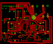
Top side of the board:
http://www.diyaudio.com/forums/attachment.php?s=&postid=971043&stamp=1154059264
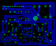
Bottom side of the board:
http://www.diyaudio.com/forums/attachment.php?s=&postid=971044&stamp=1154059327
I will make the following changes in the circuit/pcb suggested by Gajanan.
1. move the parts away from the heat sink.
2. place several PTH in power line wherever it ocures.
3. take the outgnd from one of the filter capacitor.
I will also redesign the circuits around the regulators in the PS to meet the minimal load requirements.
If you see any more troubles or mistakes with the circuits or PCB please point out.
thanks
Roushon.
The links are:
Cirsuit. http://www.diyaudio.com/forums/attachment.php?s=&postid=529675&stamp=1102598305
Power Supply.
http://www.diyaudio.com/forums/attachment.php?s=&postid=537485&stamp=1103622043
A .png file of the PCB.
http://www.diyaudio.com/forums/attachment.php?s=&postid=971042&stamp=1154059199
Top side of the board:
http://www.diyaudio.com/forums/attachment.php?s=&postid=971043&stamp=1154059264
Bottom side of the board:
http://www.diyaudio.com/forums/attachment.php?s=&postid=971044&stamp=1154059327
I will make the following changes in the circuit/pcb suggested by Gajanan.
1. move the parts away from the heat sink.
2. place several PTH in power line wherever it ocures.
3. take the outgnd from one of the filter capacitor.
I will also redesign the circuits around the regulators in the PS to meet the minimal load requirements.
If you see any more troubles or mistakes with the circuits or PCB please point out.
thanks
Roushon.
simplicity
I have seen in the thread `Three-resistor LM3886 chipamp' by Mick_F a very simple circuit around LM3886 where not even the pin 5 is connected to +V. I have now some questions if anybody please clarify.
1. Is it possible to make parallel of two such circuits without making further changes?
2. If this is true then I, now, wonder why so much cry was made in this forum about complicated circuits and even more complecated PCB design for parallel/bridge of two LM3886.
I am in this forum for sometime and learn from here quite a lot, which prompted me to go ahead with the above circuit. I have no experience about high power amplifier.
I hope someone will answer.
Regards
Roushon.
1. Yes, provided you hand match the resistors to a few ohms of each other, to ensure equal current sharing and add output resistors to each output - or use 0.1% resistors...
2. To each their own, some people want buffers, servos and nulling curcuits, regulated supplies, DC protection, etc. The idea is to go what you're comfortable with.
Remember Mick's circuit does not even have a zobel, which I consider a minimum for any amplifier myself (since I don't really know where it's going to be connected always).
I would use the datasheet circuit, and use P2P wiring. really the 3886 is too simple to wire up to even require a PCB, just 6 physical connections are required to the chip.
My 2 cents...
sangram said:1. Yes, provided you hand match the resistors to a few ohms of each other, to ensure equal current sharing and add output resistors to each output - or use 0.1% resistors...
2. To each their own, some people want buffers, servos and nulling curcuits, regulated supplies, DC protection, etc. The idea is to go what you're comfortable with.
Remember Mick's circuit does not even have a zobel, which I consider a minimum for any amplifier myself (since I don't really know where it's going to be connected always).
I would use the datasheet circuit, and use P2P wiring. really the 3886 is too simple to wire up to even require a PCB, just 6 physical connections are required to the chip.
My 2 cents...
Thanks Sangram. I have one question regarding Zobel. How does one calculate the value of the resistor and the cap in the Zobel at the output stage of an amplifier. I think one needs to know the speaker characteristic also. Or one can calculate a universal value!
I am still waiting for suggestion and criticism regarding the circuit and the pcb design from anybody. Any doubt will be helpful for me. I have all the parts to go ahead with the etching of the PCB and assemble them. Just to make sure that everything is OK before that.
Thanks and regards
Roushon.
f=1/(2*pi*R*C) where f = turnover frequency, R = resistor, C = Capacitor, pi = 3.14
f is selected first, then the C, then you can compute R.
Typically f is an iterative process, it should be high enough to keep any effects outside the audible range, and low enough so the amplifier does not go into oscillation. A lot of people don't use a zobel. I always use one, and I find a combination of 4.7 ohms + 100nF sufficient (about 340KHz) for most amps. The one PD supplies with his kits is 2.7 + 100nF, which is about 600KHz.
The zobel you're confusin it with is the one applied to the woofer terminals to equalise the rising impedance at high frequencies offered by the inductance of the voice coil, that is also called a zobel, its purpose is diferent from the one at the amp output, and it cannot stabilise an oscillating amplifier.
For that zobel you need to know the DCR and inductance of the speaker voice coil. The purpose of putting a zobel there is to ensure the series inductor in the crossover is still looking into the right impedance at high frequencies... The two can be served by the same set only if it's a full range system or one that uses no inductor on the woofer, I guess.
Like I said on your schematic, I think it's way too complex. I would ditch the regulated supply and the buffers as well, and take a regular stereo amp based on two LM3886. Then ditch the PCB as well, and assemble everything on P2P rather than PCBs.
Since there is an output resistor, I guess each half needs its own zobel.
Metal film 1/2 watt should be enough, but some designs specify 1 watt or so. Carbon film cold also be used, I don't know if it affects sound quality.
I've tried both carbon and metal film (from the spare parts bin) and cold not tell if there was a difference sonically.
Metal film 1/2 watt should be enough, but some designs specify 1 watt or so. Carbon film cold also be used, I don't know if it affects sound quality.
I've tried both carbon and metal film (from the spare parts bin) and cold not tell if there was a difference sonically.
There are some thing I really do not like about this schematic.
Why would you want to use 2 paralell input buffers??? I see the idea of using paralell LM3886, since you get more power. But you should consider feeding them from the same buffer.
Even though both buffers are identical, there will always be some difference due to production tolerances. And if the 2 LM3886's are not driven be exactely the same signal, the will work against each other.
Also you should consider using only 1 DC-servo for the system. Not one for each LM3886. Paralell circuits will always try to correct each other, and therefor work against each other.
Also consider using a low speed op-amp for DC-servo. Like LF411, OP177...
If you are still interested
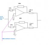
This is the simplest way to parallel lm3886 chip. There is no servo, they are not needed.
Use one half of a dual op amp per channel. The value for the resistors is up to you, I use 4.2K.
Two pins of the trimmer are connected together and one pin is connected to ground.
Before connecting the outputs check, each chips dc. Turn the trimmers until dc is zero out or as close to zero as you can get it (usually around .1 to .3 mv). Now connect the outputs together
Attachments
jaudio said:If you are still interested
This is the simplest way to parallel lm3886 chip. There is no servo, they are not needed.
Use one half of a dual op amp per channel. The value for the resistors is up to you, I use 4.2K.
Two pins of the trimmer are connected together and one pin is connected to ground.
Before connecting the outputs check, each chips dc. Turn the trimmers until dc is zero out or as close to zero as you can get it (usually around .1 to .3 mv). Now connect the outputs together
Thanks a lot for your suggestion. But if the dc is made zero by this procedure, I do not know whether it will have some negative effect on the sound quality. I am curious because I have not seen this method before in any of the application notes of NS. There they always suggest to use a dc-servo when paralleling.
In any case I will try it also.
jaudio said:
The value for the resistors is up to you, I use 4.2K.
The value for the resistors is up to you, I use 4.2K4.2k and 57.7k resistors
jaudio said:Two pins of the trimmer are connected together and one pin is connected to ground.
.
Two pins of the trimmer are connected together , then connected to the (+) signal input and the third pin is connected to ground
I have not heard any negative effects
making the pcb
no comments so far...
regarding making the pcb I contacted some company here in mumbai. they need the order for at least 10 pcbs. I need only 2. would anybody like to join me for the pcb, if interested in the circuit? I am not trying to make a group buy, need to give away the remaining 8 and only within India. i do not know any other company who will make only 2 for me. if anybody has some information please share.....
thanks
- Status
- This old topic is closed. If you want to reopen this topic, contact a moderator using the "Report Post" button.
- Home
- Amplifiers
- Chip Amps
- PCB design of parallel of two inverted LM3886 with buffer and dc-servo.