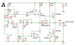
Your amp looks like voltage feedback to me, and the cap is totally appropriate. Without it, stray capacitance can be seen as a capacitor from Q1's emitter to ground, which causes an increase in gain and instability at HF. The 5p cap swamps these out to improve stability.
- keantoken
- keantoken
I see...
What do you say about this amp? http://sound.westhost.com/project12.htm
Looking at R4, it is not a low value and neither is the feedback resistor R5, so why is it still called a current feedback amp?
thanks
What do you say about this amp? http://sound.westhost.com/project12.htm
Looking at R4, it is not a low value and neither is the feedback resistor R5, so why is it still called a current feedback amp?
thanks
Last edited:
I've been wondering the same thing since I did a google search on current feedback amplifiers. It's the same concept as a voltage amplifier, just done a different way. Maybe a creative way to get a patent...?
There is no current or voltage feedback, only impedance feedback since mortals can't measure pure voltage or pure current.
I think the major difference is in the compensation. In current feedback amplifiers the compensation is done in such a way that the OLG corner frequency is higher so we have a faster amp, and it rolls off steeply. But AFAIK, this can be done in a voltage feedback amp as well. Differences in performance are accounted for not because of the benefits of "current feedback", but rather because the component stray parasitics are arranged differently and open up doors for different applications. (maybe the difference is that between inductive input impedance and capacitive input impedance?)
I'm certainly no expert and I'm still not sure (need more time to think), maybe I'm making a fool out of myself but this seems to be a case of "much ado".
- keantoken
See, I'm not the only one wondering. In the article, Quoth Rod:
- keantoken
The most notable difference between this amp and more modern versions is the fact that there is no long-tailed pair (LTP) for the front end. Feedback is applied to the emitter of the input transistor, and works in current mode - hence 'current feedback'. This is possibly contentious - there are several interpretations of the term 'current feedback', and not everyone agrees. In this case, the emitter circuit of a transistor is inherently very low impedance, so is influenced by current. That the current is derived from a voltage is of little consequence, because this is the case for nearly all feedback circuits.
- keantoken
Thanks for pointing that out. This really is interesting!
Whatever kind of feedback it may be, it works magic. For newbies like me CFB or VFB doesn't matter, as long as the machine sounds good.
I'm in audio electronics for a mere 10+ years and before I knew anything about the difference between VFB and CFB all the amps I made in the first five years were VFB(now I know). Unfortunately, none of those amps sounded good to me. I sold most of them, the customers were satisfied with them, very much.
This preamp+follower combo was my first attempt into single transistor input non inverting emitter feedback amps, it was four years back from now. Noticing the 'alien' sound quality I started to read further and after four years of reading I found that LTP+Current Source+Current Mirror is "the" way to go for true hi-fi sound. That said, the best amp I ever heard till now is a single BJT input amp. This amp.
I found the LTP amps good for sub-woofers. But they are anemic in the 10kHz+ region. There this amp shines. Not counting the soothing mid range.
Maybe all I seem to be talking about is the "nice" low-order distortions, then, I know that I want to make my amp as clean as possible, and have made many which have THD of less than 0.05% at close to full power. Much lower than this follower. They sound hollow, both at bias of 200mA or 2A, and they are all LTP type. Also the amps I made in the first five years were all LTP type.
P.S.- I am excluding the LM3886, LM1875 etc. from this, they are mysterious, and should be treated with respect. Alas, I cannot make copies of them in my home from spare parts.
Last edited:
I think I sound crazy saying this, but if you look into MikeB's Symasym, which uses a double LTP, he says there was a big difference in quality when he changed to the 2N5551 and 5401 transistors. Perhaps it partly depends on the transistors?
Also, you may want to play with R9 as well to help square waves (if it matters). This resistor, aside from being a gate-stopper, forms part of an RC network from the output of your preamp to ground (through MOSFET parasitics). This network is what stabilizes your preamp without needing a Cdom on Q2. This nonstandard compensation gives your amp the qualities of a current feedback amp (high open-loop corner frequency, fast, steep rolloff). I like this, and I wonder what it has to do with the sonics. Is it possible that different compensation could be partly responsible for better sonics? Thinking out loud... You could test this by giving Q2 a Cdom, say 33-68pF.
- keantoken
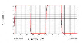
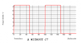
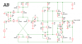
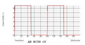
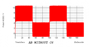
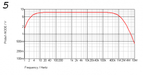
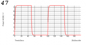
Here they are. With the LTP one too.
Addition of the Cdom in the emitter feedback amp seems to make it anemic in the HF response.
Removal of the Cdom from the LTP amp seems to make it run so fast that it starts to fly at supersonic speed.
These tell little about the sonics, however, everybody knows these facts.
Addition of the Cdom in the emitter feedback amp seems to make it anemic in the HF response.
Removal of the Cdom from the LTP amp seems to make it run so fast that it starts to fly at supersonic speed.
These tell little about the sonics, however, everybody knows these facts.
Attachments
The typical VAS Cdom loads the input stage inefficiently, and so for a BW of 10MHz you may have a corner frequency of 1KHz, probably lower, right in the middle of the audio range which explains why especially the treble may sound worse. You may be interested in my headphone amp. It uses an alternative to the LTP input stage which has the same transfer curve as your single transistor input, and a similarly unconventional stabilization scheme.
http://www.diyaudio.com/forums/headphones/159815-rush-cascode-headphone-amp-jlh-output-stage.html
- keantoken
http://www.diyaudio.com/forums/headphones/159815-rush-cascode-headphone-amp-jlh-output-stage.html
- keantoken
The typical VAS Cdom loads the input stage inefficiently
That is a good reason to isolate the input pair from cdom (vas)with a cascode or go all the way and use a folded cascode VAS.
OS
I mean the C-B miller cap.
So do I. Cdom = miller cap = dominant pole of amp. Without it the Cob of the vas tranny would be dominant and you would oscillate in the Mhz !
On either a current sourced VAS or a balanced one, Cdom (the miller cap) can load or unbalance the input pair. This is obvious on either a simulation or a scope. On a old transistor (mje340/50) , just the Cob (parasitics) can load a LTP enough to make it non-linear.
OS
The input pair drives the cascode and there IS a still a load. What the cascode does is isolate the inputs from the undesirable effects of the miller capacitance.How does a cascode reduce current loading?
This technique was first used with vacuum tubes long ago.
OS
Ostripper, you caught me before I edited my post.
I understand what you mean, and you've reiterated my point about Cdom loading.
[if I understand correctly]
Unfortunately, simply using both legs of the LTP only divides Cdom loading. It does not improve it's efficiency. If I understand correctly, what happens is that the gain of the LTP is halved at most at HF, which may not be enough to get the circuit stable. In any case, what I'm suggesting is a better alternative to the VAS miller cap type of Cdom. In this case, upgrading the horse does not reconcile a slow carriage.
I am not suggesting a panacea. Different applications give different demands.
- keantoken
The input pair drives the cascode and there IS a still a load. What the cascode does is isolate the inputs from the undesirable effects of the miller capacitance.
This technique was first used with vacuum tubes long ago.
OS
I suppose it depends on what kind of VAS you use. For my VAS's, any Cdom value will swamp out parasitics and render them negligible. I consider this beneficial, since semiconductor parasitics are nonlinear.
- keantoken
alternative to the VAS miller cap type of Cdom.
Folded cascode VAS. Still has a miller , but between the collector and ground. This eliminates the parasitic entirely.
This works on the input cascode , too . With a current sourced cascode both the miller and parasitic capacitance of the VAS is invisible to
the LTP.
OS
Attachments
Last edited:
Ostripper, I'm talking about stability compensation, in the form of a discrete miller cap, just like C7 of Shaan's latest follower schematic.
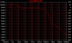
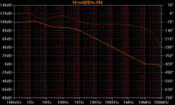
Here is what I mean about being inefficient. These are two open-loop plots from an old version of my headamp. The first is with default compensation. Second is switched to the VAS miller cap Cdom like Shaan's schematic. OLG is a function of differential voltage of the input stage, which is a function of input stage loading. As you can see, for the same phase margin, my alternate compensation scheme is much much more "discrete". Input stage loading effects are outside the audio spectrum, and THD is low at ultrasonics.
- keantoken
Attachments
Last edited:
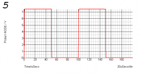
The sim shows overshoot with 10kHz square wave. The small cap (C6) solved it. At the same time I have some silver mica 5pF I bought years ago. Installed them in the board. No impact on speaker output though. Same lucid sound.
I heard this feedback cap causes current feedback amps to oscillate. Perhaps it wasn't true.
cheers.
Hi,
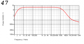
I also add silver Mica there, but not 5pf, but 47pF. Don't know any issue afterward, but seems OK if I test through free PC software (RTA) using soundcard + pink noise.
Ervin L
Hi,
I also add silver Mica there, but not 5pf, but 47pF. Don't know any issue afterward, but seems OK if I test through free PC software (RTA) using soundcard + pink noise.
Ervin L
5 Vs 47.
Real world performance will be poorer in both cases though.
Attachments
- Status
- This old topic is closed. If you want to reopen this topic, contact a moderator using the "Report Post" button.
- Home
- Amplifiers
- Solid State
- Pavel's MOSFET Follower - No Darlington Mod