Make yourself a favour, try to find one of these bargains:
Russian K73-16B PETP Capacitors 22uF 10% 63V, Lot of 48 - eBay (item 250555634815 end time Mar-29-10 16:25:22 PDT)
These are what I am using now") Sound good.
Sound good.
Cheers,
M.
Russian K73-16B PETP Capacitors 22uF 10% 63V, Lot of 48 - eBay (item 250555634815 end time Mar-29-10 16:25:22 PDT)
These are what I am using now
Sound good. Cheers,
M.
Fortunately, i got them for free....
Attachments
I'm using Keltron elctros in my MPF's output. They are the most expensive caps in my nearest shops. They sound good! I think bigger shops will have better and more expensive ones. I'm gonna use it in high pass of the system, so 4700uF is fine. Now I am searching for Phillips 10uF film caps.
Sorry shaan, i haven't been following this thread & just kind of jumped in
I'm assuming you are still discussing this output stage with a mosfet as the output. In which case the extremely high current gain doesn't really help, no. The mosfet will require a higher gate voltage to supply more current & this will result in a loss in gain. So assuming it was running an 8ohm speaker or load previously it might need an extra volt or so on the gate of the mosfet to drive the 4ohm load. This will obviously result in the same kind of loss on the output unless the gate drive is increased.
A way round it is to employ a mosfet with much higher transconductance. I'd suggest as low a voltage mosfet as possible given the rail voltage. If operating on +/-25V a 55 or 60V mosfet would be better than a 100V device as long as you get one with as low an RDS on resistance as possible
Might not be as easy to drive due to increased capacitance but there will be less difference between input & output of the source follower.
Hi people! Long time no see!
A question...
Why does the follower decreases output power when load is decreased to 4ohm from 8ohm? Is this a property of a voltage controlled voltage source? Or something else?
It is a rule of a single-ended class A output stage.
You get Pout = 0.5*Rload*Iq*Iq
where Iq ... CCS idle current
The same for any SE class A supplied by CCS or resistor or inductor.
If you need more, go push-pull class A or Pass Aleph regulated CCS.
Ah yes, as PMA has pointed out, unless your current sink is capable of sinking all the current to swing a certain voltage it'll produce less output power.
In other words make sure that you increase the current
The source follower will still need a higher drive voltage to supply the current to the load though
In other words make sure that you increase the current
The source follower will still need a higher drive voltage to supply the current to the load though
Ah yes, as PMA has pointed out, unless your current sink is capable of sinking all the current to swing a certain voltage it'll produce less output power.
In other words make sure that you increase the current
Increasing Iq will result in more 4ohm power? Ya... I think I understand now. Ya, once I decreased the supply voltage and doubled the Iq through the follower. With 20V supply and 3.5A, the 4ohm speaker sounded much louder, but clipped earlier.
The source follower will still need a higher drive voltage to supply the current to the load though
How can I get around it? Will using a higher supply voltage for the DoZ preamp help? Like 40V for the follower and 60V for the preamp?
As Pavel mentioned the current sink (i say sink as you are using a source follower) will need to be increased in current value to make sure you can swing the full voltage into a 4 ohm load. If you went push pull as Pavel suggested then you could bias at half the quiescent current than you'd need for a single ended output stage. Please remember that the current sink needs to draw all the current that the load is ever going to need. A 4ohm speaker may well dip below 2ohms so set the current accordingly. With a push pull stage there isn't really any possibility of early clipping due to not enough bias current as the output stage can operate in class B above a certain point. A single ended stage can't, it'll just clip early if there isn't enough quiescent current.Increasing Iq will result in more 4ohm power? Ya... I think I understand now. Ya, once I decreased the supply voltage and doubled the Iq through the follower. With 20V supply and 3.5A, the 4ohm speaker sounded much louder, but clipped earlier.
How can I get around it? Will using a higher supply voltage for the DoZ preamp help? Like 40V for the follower and 60V for the preamp?
E2A:- on negative going waveforms it'll clip early if not enough quiescent current.
Yes you'll need a higher drive voltage whether it is driving an 8 or 4ohm load. More if driving a lower impedance load & a lowish transconductance mosfet. I'd suggest a 10V overdrive from a preamp would cover it. Make sure you fit a zener or similar protection from gate to source on the source follower so you don't blow the gate
Last edited:
Can I modify/add this SE Power Follower to Push Pull, by adding R series in top side (from drain mosfet to V+), and in R below CCS/current sense (connecting this R to 0), both with the same value, and then connect voltage generated from this R (e.g., Iq = 2.2A, R = 1 Ohm, V = 2.2 V), to drive Gate-Source of Complementary MOSFET. Then both of drain of MOSFET pair is connected, output to speaker via coupling caps. Will this work?
Mathematically, the MOSFET pair will be balance, and the drain voltage is half of V+ and V-/0, and may swing as there is signal driving MOSFET of power follower.
Thanks,
Ervin L
Mathematically, the MOSFET pair will be balance, and the drain voltage is half of V+ and V-/0, and may swing as there is signal driving MOSFET of power follower.
Thanks,
Ervin L
Won't it transformer degrade the sound? I think buying a great Elna(or any great make) cap at half the price of the transformer would be better...
cheers/
What kind of ELNA will fit for this purpose? I use ELNA 105 currently. Considering Cerafine and Silmic, but none has higher uF (unless parallel it - costly). Most feasible price may be Elna for Audio (6800 uF exists), or Nippon Chemicon (Yamaha, Denon).
Not sure if Nichicon Muse KG will fit best for this position.
I don't bypass the Elco yet, if so, what is best? I try to bypass with Jantzen Cross Caps (18uF) but my ear still can't see the difference
Also tried WIMA MKP 1uF.Thx,
Ervin L
Cascode mod of the CCS. Just a thought. Are we really allowed to do this? I mean, does it seem to be workable? I ran a simulation with the current probe placed on the +ve of the 1ohm resistor(marked with black arrow). Above is the schematic and below is the graph.
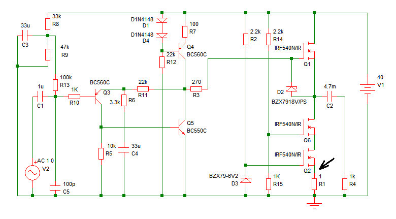
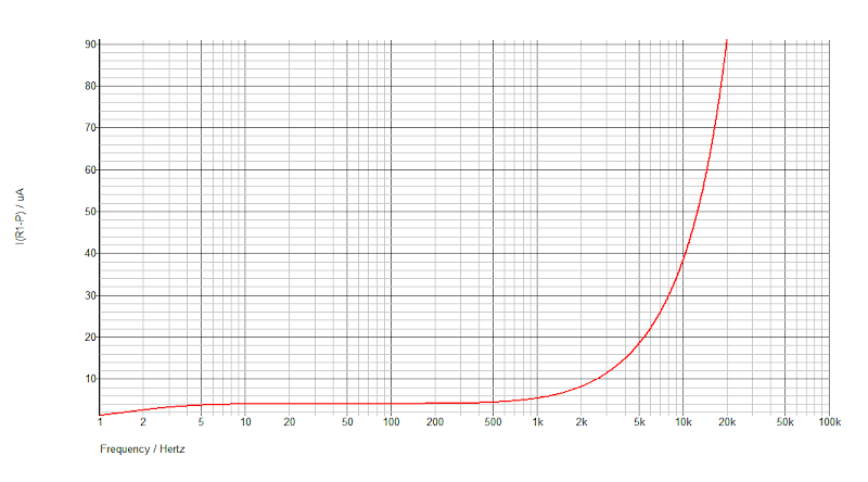
About 90 microampere at 20kHz. Does it mean fluctuation of 90uA? As much as I know It is not the quiescent current, because the original MPF with darlington shows 15mA at 20kHz in the same test but draws 2.2A from the supply. As 90uA is about 166 times smaller than 15mA so I was wondering whether it could minimize the spikes further or not. Need advice.
Thanks.
What if R11 (22k) not connected to the pre amp output, but direct it to MOSFET Q1 source (before to output caps)? Will it improve?
Thx.
Can I modify/add this SE Power Follower to Push Pull
I think your proposal is for a type of White Cathode Follower for solid state? I have never seen it done for a power amplifier, however I think it is possible in theory. There is a small signal version detailed in this document: http://www.borbelyaudio.com/adobe/ae699bor.pdf
See Figure 16A, on page 3.
....I have never seen it done for a power amplifier...
Closest to that comes the output stage in Aleph series of amplifiers (Aleph CCS) done by Mr. Pass - Pass Labs section of this forum is full of infos about it.
Closest to that comes the output stage in Aleph series of amplifiers (Aleph CCS) done by Mr. Pass - Pass Labs section of this forum is full of infos about it.
Hi Juma, I have started to read some threads in the Pass Labs section and they are very interesting (including your own posts / designs). The problem is so much information and so little time!!! I must go and read some more... so it will be the Aleph threads next. Thank you.
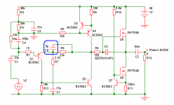
I had some thoughts about this circuit:
Why not make the positive rail ground? When the circuit switches on, Q1 will dump an indefinite amount of current into C2 in order to bring the output up. If the load is instead connected to +rail, the CCS will instead draw a steady current through the load until the cap is fully charged, minimizing turn-on thump.
After we do this, I had the funny thought of experimenting with connecting the ground side of C4 to Q4's emitter. That way the current source becomes a linear push-pull follower, conserving energy without damaging linearity. (Also, the feedback network was the only thing loading the VAS, now it doesn't anymore...)
Also, if you want to see the real response of the CCS you will have to place the current probe at Q6's collector (BJT terms for lack of MOSFET vocabulary...). The current through R1 will in fact be the most steady since MOSFET capacitances reroute error currents to the gates.
- keantoken
Last edited:
Small addition
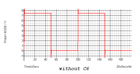
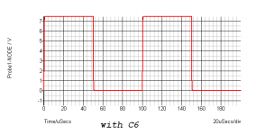
The sim shows overshoot with 10kHz square wave. The small cap (C6) solved it. At the same time I have some silver mica 5pF I bought years ago. Installed them in the board. No impact on speaker output though. Same lucid sound.
I heard this feedback cap causes current feedback amps to oscillate. Perhaps it wasn't true.
cheers.
Attachments
- Status
- This old topic is closed. If you want to reopen this topic, contact a moderator using the "Report Post" button.
- Home
- Amplifiers
- Solid State
- Pavel's MOSFET Follower - No Darlington Mod