I got 2 PCB's as well yesterday, thanks!
Before I begin soldering: To power by DC but build complete, stock PA-03 boards, would it work if I connect my DC source to the ~ terminals of the bridge rectifier? What I think I don't understand is if the delayed-on circuit could cause trouble if it doesn't receive AC-pulses to count.
Before I begin soldering: To power by DC but build complete, stock PA-03 boards, would it work if I connect my DC source to the ~ terminals of the bridge rectifier? What I think I don't understand is if the delayed-on circuit could cause trouble if it doesn't receive AC-pulses to count.
If you don't have 50/60 Hz AC in, your delay circuit won't work but it's not that hard to create an oscillator for that.
Thanks again!
Hello Per-Anders!
I realised that I forgot to ask you 8 inductors for my 4 boards...
I tried to find it in the wiki page but didn't find it there.
Could you please send me a paypal invoice and the specifications of it?
Also... what do you think about populating the boards with Dale RN55D resistors?
Thank you!
I realised that I forgot to ask you 8 inductors for my 4 boards...
I tried to find it in the wiki page but didn't find it there.
Could you please send me a paypal invoice and the specifications of it?
Also... what do you think about populating the boards with Dale RN55D resistors?
Thank you!
Hello Per-Anders!
I realised that I forgot to ask you 8 inductors for my 4 boards...
I tried to find it in the wiki page but didn't find it there.
Could you please send me a paypal invoice and the specifications of it?
Also... what do you think about populating the boards with Dale RN55D resistors?
Thank you!
Specs: Inductor, 0.7-1.5 uH, 15 turns Ø1.3-1.4 on dia Ø8.
Here you can find are all the documents:
Docs
Schematics
BOM
Made some progress yesterday
 Can't wait to power it on!
Attachments
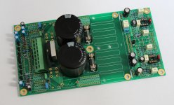
Made some progress today . The board is almost completely done. However, I still have to order a mica insulation sheet for the LM4780 and to solder the two voltage regulators to the board. In addition I will add two extra spacers to attach the heatsink even more firmly to the PCB. There are already a few holes for that in the PCB. I changed the layout for the heatsink a bit. This way the cabinet can still be 'low profile' and does not have to be that large in size.
. The board is almost completely done. However, I still have to order a mica insulation sheet for the LM4780 and to solder the two voltage regulators to the board. In addition I will add two extra spacers to attach the heatsink even more firmly to the PCB. There are already a few holes for that in the PCB. I changed the layout for the heatsink a bit. This way the cabinet can still be 'low profile' and does not have to be that large in size. An externally hosted image should be here but it was not working when we last tested it.
.JPG)
An externally hosted image should be here but it was not working when we last tested it.
.JPG)
An externally hosted image should be here but it was not working when we last tested it.
.JPG)
An externally hosted image should be here but it was not working when we last tested it.
.JPG)
An externally hosted image should be here but it was not working when we last tested it.
.JPG)
Last edited:
Update: I was searching in my 'junk box' for some parts when I saw a nice U shaped piece of 5 mm thick aluminium. So after some drilling and tapping some new M3 holes the PCB has been improved . I have also added two spacers for extra stability.
. I have also added two spacers for extra stability.An externally hosted image should be here but it was not working when we last tested it.
An externally hosted image should be here but it was not working when we last tested it.
An externally hosted image should be here but it was not working when we last tested it.
Group buy
Very nice implementation of the heatsink, I was thinking along the same lines as I was searching for a suitable enclosure, to mount the board horizontally narrows the choice of enclosure.
Hence the cost goes up.
Incidentally, PER, if you're reading this, I'd like to go ahead with the white PCB but your inbox is full.
Good show everyone!
Hi! Quick question:
In the elfa BOM, C2, 3, 6 and 7 (68pF, 500V) are listed as article no 65-862-00, which turns out to be 47 pF 100V.
C9, 16 (47pF, 500V) are listed as article no 65-862-26, which turns out to be 68pF, 100V.
My bad for not reading properly what I ordered, so now I have slightly wrong parts.
My questions are:
Is the lower voltage rating ok?
If so, since I ordered just enough parts, is the small difference in capacitance vary important or can I just put the 68pF ones where 47pF ones would go and vice versa?
Otherwise my build is progressing nicely, heat sinks tapped without incident=)
Best regards!
- Home
- Group Buys
- Pavel Dudek's super Gainclone group buy