You might seriously want to consider
4th order L-R for a sub
I had 2nd order on my plate amps and they never did integrate well. Same drivers using a Crown amp and digital crossover integrate beautifully with 4th order L-R, and did very well with 4th order Butterworth, inverted phase while they never integrated well with any of the lower order combinations that I tried.
My general impression has been that higher order crossovers are used a good bit with subs, so you might want to consider 4th order.
Of course this is dependent on drivers, crossover point, cabinets, etc. so YMMV.
I did scan this thread but didn't read it in detail so pardon me if I missed something on this.
Regards
Ken l
Ken L, I agree with you - I use 4th-order LR myself. However, I think matttcattt is just trying to knock something simple together to start with.
matttcattt, I assume you are bridging the chip amps? I personally wouldn't build that P77 PSU as it is single-ended, i.e. only 12v and ground, which will give you a bit of hassle when you come to use Linkwitz Transforms and better filters. All you need is a split-secondary (maybe 12-0-12, 110va) transformer, bridge rectifier and a couple of caps maybe 4700uF. 25 amps is WAY overkill and you will never use that capacity.
As for the L+R summing, I always use an inverting mixer cct like that shown on the P71 pages. This also includes a phase switch, which is most definitely necessary IMO.
Re: You might seriously want to consider
i want to try a higher order filter, yes.
no, 4 chips parrelleled.
the PSU is ALTERED, have a look at the diagram here: http://img.villagephotos.com/p/2003-11/479639/10APSU.gif
when i first fired up the amp, it had only 8 chips connected, and it drew 6A from the PSU (5A limited PSU), at low volume, pushing it, the power supply sagged, and the output went right down. with 16 chips, the amp only plays really low volume. i do need the current.
is the summing/buffer circuit really needed? im not one of those "no opamps in the signal path" people, but there isnt really enough space for extra boards if they are not needed.
Ken L said:4th order L-R for a sub
I had 2nd order on my plate amps and they never did integrate well. Same drivers using a Crown amp and digital crossover integrate beautifully with 4th order L-R, and did very well with 4th order Butterworth, inverted phase while they never integrated well with any of the lower order combinations that I tried.
My general impression has been that higher order crossovers are used a good bit with subs, so you might want to consider 4th order.
Of course this is dependent on drivers, crossover point, cabinets, etc. so YMMV.
I did scan this thread but didn't read it in detail so pardon me if I missed something on this.
Regards
Ken l
i want to try a higher order filter, yes.
richie00boy said:Ken L, I agree with you - I use 4th-order LR myself. However, I think matttcattt is just trying to knock something simple together to start with.
matttcattt, I assume you are bridging the chip amps? I personally wouldn't build that P77 PSU as it is single-ended, i.e. only 12v and ground, which will give you a bit of hassle when you come to use Linkwitz Transforms and better filters. All you need is a split-secondary (maybe 12-0-12, 110va) transformer, bridge rectifier and a couple of caps maybe 4700uF. 25 amps is WAY overkill and you will never use that capacity.
As for the L+R summing, I always use an inverting mixer cct like that shown on the P71 pages. This also includes a phase switch, which is most definitely necessary IMO.
no, 4 chips parrelleled.
the PSU is ALTERED, have a look at the diagram here: http://img.villagephotos.com/p/2003-11/479639/10APSU.gif
when i first fired up the amp, it had only 8 chips connected, and it drew 6A from the PSU (5A limited PSU), at low volume, pushing it, the power supply sagged, and the output went right down. with 16 chips, the amp only plays really low volume. i do need the current.
is the summing/buffer circuit really needed? im not one of those "no opamps in the signal path" people, but there isnt really enough space for extra boards if they are not needed.
Matttcattt,
Without bridging and using the 15 volt supply you propose, you are never going to get any more than about 28 watts peak into the 8 ohm drive unit you are using, even if you parallel 100 chips...
Also, the power supply you propose is unnecessarily complex for the task. As I said above, all you need is a bridge rectifier and 4700uF caps would be plenty for upto 100 w peak.
If you are trying to avoid op-amps in the signal path, you will do more 'damage' by trying to use passive filters throughout. Also, you will have problems implementing a 4th-order filter passively. I find your logic a little strange that you don't want to use op-amps in the signal path when you are happy using chip amps as a sub amp, paralleling all those chips together, it's not really the best way.
You would end up with a much simpler and smaller design if you used the simple PSU I proposed and a P3A or similar. And the results would probably be better.
richie00boy said:Matttcattt,
Without bridging and using the 15 volt supply you propose, you are never going to get any more than about 28 watts peak into the 8 ohm drive unit you are using, even if you parallel 100 chips...
Also, the power supply you propose is unnecessarily complex for the task. As I said above, all you need is a bridge rectifier and 4700uF caps would be plenty for upto 100 w peak.
If you are trying to avoid op-amps in the signal path, you will do more 'damage' by trying to use passive filters throughout. Also, you will have problems implementing a 4th-order filter passively. I find your logic a little strange that you don't want to use op-amps in the signal path when you are happy using chip amps as a sub amp, paralleling all those chips together, it's not really the best way.
You would end up with a much simpler and smaller design if you used the simple PSU I proposed and a P3A or similar. And the results would probably be better.
why cant i get more than about 28
W peak?
for the size toroids i can get (300-500VA), the lowest voltage is 25v, so i basically need voltage rectification.
i said i am NOT one of those "no opamps in the signal path people".
I am not interested in a P3A, or the size, or performance, or simlicity difference. i just want to know about filters for THIS amp.
")
I will post an amp later today, when i have had a chance to make one.
Apologies for my lack of reading skills. It was Monday morning...
You won't get more power just by paralleling more chips. The powers don't just simply add together to get more and more. It's simple ohms law - there is only so much current that you can force through an 8 ohm load with 15 volts.
I = V / R = 15 / 8 = 1.875 amps
P = V * I = 15 * 1.875 = 28.125 watts
Or more quickly, P = V^2 / R = (15 * 15) / 8 = 28.125
Going by my modelling earlier that your sub will only handle (in the frequency range you intend to use it) about 40 watts RMS, which is 80 watts peak, and re-arranging the formula above to find what voltage you need:
V = sqrt(P * R) = sqrt(80 * 8) = 25.3 volts
Add 10% for o/p stage losses = 27.8 volts
The chip you are using will (just) handle this voltage, but looking at the safe operating area graph on the datasheet, it will not handle the power at this voltage (I'm using the 85C curve as it WILL run hotter than 25C). It will handle about 47W, so parallel 2 chips together *to share the current* and give you 94W in total as *handling capacity*. It doesn't mean that you can get 94W with that load.
I'm guessing you meant regulation A 300 va toroid will be PLENTY.
Are you getting *all* the parts for free? Unless you are, it would be cheaper and simpler to buy a lower voltage (18-0-18 would be OK) toroid at maybe £18, than the transistors and LARGE heatsink that your proposed regulated supply needs...
As for filters, if you are intending to do some upgrading, it might be best to leave the chip amp as per app note (or whatever) and make a separate active filter board. Then fiddling is easier and safer.
You won't get more power just by paralleling more chips. The powers don't just simply add together to get more and more. It's simple ohms law - there is only so much current that you can force through an 8 ohm load with 15 volts.
I = V / R = 15 / 8 = 1.875 amps
P = V * I = 15 * 1.875 = 28.125 watts
Or more quickly, P = V^2 / R = (15 * 15) / 8 = 28.125
Going by my modelling earlier that your sub will only handle (in the frequency range you intend to use it) about 40 watts RMS, which is 80 watts peak, and re-arranging the formula above to find what voltage you need:
V = sqrt(P * R) = sqrt(80 * 8) = 25.3 volts
Add 10% for o/p stage losses = 27.8 volts
The chip you are using will (just) handle this voltage, but looking at the safe operating area graph on the datasheet, it will not handle the power at this voltage (I'm using the 85C curve as it WILL run hotter than 25C). It will handle about 47W, so parallel 2 chips together *to share the current* and give you 94W in total as *handling capacity*. It doesn't mean that you can get 94W with that load.
for the size toroids i can get (300-500VA), the lowest voltage is 25v, so i basically need voltage rectification.
I'm guessing you meant regulation
A 300 va toroid will be PLENTY.Are you getting *all* the parts for free? Unless you are, it would be cheaper and simpler to buy a lower voltage (18-0-18 would be OK) toroid at maybe £18, than the transistors and LARGE heatsink that your proposed regulated supply needs...
As for filters, if you are intending to do some upgrading, it might be best to leave the chip amp as per app note (or whatever) and make a separate active filter board. Then fiddling is easier and safer.
richie00boy said:Apologies for my lack of reading skills. It was Monday morning...
You won't get more power just by paralleling more chips. The powers don't just simply add together to get more and more. It's simple ohms law - there is only so much current that you can force through an 8 ohm load with 15 volts.
I = V / R = 15 / 8 = 1.875 amps
P = V * I = 15 * 1.875 = 28.125 watts
Or more quickly, P = V^2 / R = (15 * 15) / 8 = 28.125
Going by my modelling earlier that your sub will only handle (in the frequency range you intend to use it) about 40 watts RMS, which is 80 watts peak, and re-arranging the formula above to find what voltage you need:
V = sqrt(P * R) = sqrt(80 * 8) = 25.3 volts
Add 10% for o/p stage losses = 27.8 volts
The chip you are using will (just) handle this voltage, but looking at the safe operating area graph on the datasheet, it will not handle the power at this voltage (I'm using the 85C curve as it WILL run hotter than 25C). It will handle about 47W, so parallel 2 chips together *to share the current* and give you 94W in total as *handling capacity*. It doesn't mean that you can get 94W with that load.
I'm guessing you meant regulation
Are you getting *all* the parts for free? Unless you are, it would be cheaper and simpler to buy a lower voltage (18-0-18 would be OK) toroid at maybe £18, than the transistors and LARGE heatsink that your proposed regulated supply needs...
As for filters, if you are intending to do some upgrading, it might be best to leave the chip amp as per app note (or whatever) and make a separate active filter board. Then fiddling is easier and safer.
how can i tell how much voltage the driver can handle?
regulation, thats the word
what are the advantage/disadvantages of having a toroid with a few capacitors etc over having a regulated supply? i wanted a reglated supply so the rails wouldnt change with the output current, and also so that i could use it for a car battery charger (as rod says it can). im not getting all the parts free by the way, just the chips, i have to pay for the rest
.i havent actually finished the amplifier, as it has no power supply, and the inputs are not connected to anything yet, so i can do some serious changes if they will improve make it better. im not willing to take each chip out and completely re-wire them for example, but adding a capacitor across the feedback resistor is fine.
You can work out the max voltage the driver can handle from it's power rating, which is listed as 350 watts RMS. This is the voice coil thermal rating though, it doesn't mean you can shove 350 watts through it at any frequency, unless you want to tear it apart
If you only got the chips free then definitely do not build a regulated supply - the heatsink alone will cost you as much as most of the parts to build a simple PSU! It will also be quite big and get quite warm. The single advantage is that the voltage is pretty stable, but this is not that important with a chip amp as they have very good PSRR - power supply rejection ratio. It can be argued that the regulators make the impedance of the supply WORSE than a simple unregulated one. There's also more to go wrong and potential for expensive mishaps later down the line...
If you only got the chips free then definitely do not build a regulated supply - the heatsink alone will cost you as much as most of the parts to build a simple PSU! It will also be quite big and get quite warm. The single advantage is that the voltage is pretty stable, but this is not that important with a chip amp as they have very good PSRR - power supply rejection ratio. It can be argued that the regulators make the impedance of the supply WORSE than a simple unregulated one. There's also more to go wrong and potential for expensive mishaps later down the line...
richie00boy said:You can work out the max voltage the driver can handle from it's power rating, which is listed as 350 watts RMS. This is the voice coil thermal rating though, it doesn't mean you can shove 350 watts through it at any frequency, unless you want to tear it apart
If you only got the chips free then definitely do not build a regulated supply - the heatsink alone will cost you as much as most of the parts to build a simple PSU! It will also be quite big and get quite warm. The single advantage is that the voltage is pretty stable, but this is not that important with a chip amp as they have very good PSRR - power supply rejection ratio. It can be argued that the regulators make the impedance of the supply WORSE than a simple unregulated one. There's also more to go wrong and potential for expensive mishaps later down the line...
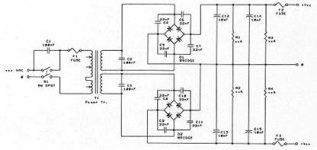
so you think i should make something like this? i have 4 33,000uf caps, so 66,000uf per rail...
Attachments
sorry about the double post. 
i hope i have the right idea.
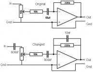
the 800nf are really 470 and 330 paralleled, just for simplicity.
feel free to change the diagram/call me stupid if i have got it wrong. the info is scattered across several posts.
thank you so much for your help so far.
[edit]: duh! forgot the image.
i hope i have the right idea.
the 800nf are really 470 and 330 paralleled, just for simplicity.
feel free to change the diagram/call me stupid if i have got it wrong. the info is scattered across several posts.
thank you so much for your help so far.
[edit]: duh! forgot the image.
Attachments
The PSU schematic you have is OK, if a bit on the complex-for-what-you-need side. There's no need to use 2 bridge rectifiers (as you will get 50Hz instead of 100Hz ripple, which is harder to filter out), or that many snubber caps across the bridges AND transformers, or the bleed resistors across the caps (as the amp will discharge the caps anyway).
Is perfect for what you need (using 18-0-18 not 25). Add more capacitance if you want, but I'd be tempted to save a couple of those big caps of yours for another project. Also EITHER add 47nF caps across each diode of the bridge, or 100nF across each side, i.e. ac and dc.
Your amp schematic looks fine with the exception of the 800nF caps. Leave the one on the pot wiper at 800nF and either make the input one 10uF or ditch it altogether, as the CD player will have an output cap anyway.
You could also add a 470nF across the pot and then put a 4k3 in line to the input to add another (passive) low-pass filter, to make it 12dB/oct overall with the active filter on the amp.
An externally hosted image should be here but it was not working when we last tested it.
Is perfect for what you need (using 18-0-18 not 25). Add more capacitance if you want, but I'd be tempted to save a couple of those big caps of yours for another project. Also EITHER add 47nF caps across each diode of the bridge, or 100nF across each side, i.e. ac and dc.
Your amp schematic looks fine with the exception of the 800nF caps. Leave the one on the pot wiper at 800nF and either make the input one 10uF or ditch it altogether, as the CD player will have an output cap anyway.
You could also add a 470nF across the pot and then put a 4k3 in line to the input to add another (passive) low-pass filter, to make it 12dB/oct overall with the active filter on the amp.
richie00boy said:The PSU schematic you have is OK, if a bit on the complex-for-what-you-need side. There's no need to use 2 bridge rectifiers (as you will get 50Hz instead of 100Hz ripple, which is harder to filter out), or that many snubber caps across the bridges AND transformers, or the bleed resistors across the caps (as the amp will discharge the caps anyway).
An externally hosted image should be here but it was not working when we last tested it.
Is perfect for what you need (using 18-0-18 not 25). Add more capacitance if you want, but I'd be tempted to save a couple of those big caps of yours for another project. Also EITHER add 47nF caps across each diode of the bridge, or 100nF across each side, i.e. ac and dc.
Your amp schematic looks fine with the exception of the 800nF caps. Leave the one on the pot wiper at 800nF and either make the input one 10uF or ditch it altogether, as the CD player will have an output cap anyway.
You could also add a 470nF across the pot and then put a 4k3 in line to the input to add another (passive) low-pass filter, to make it 12dB/oct overall with the active filter on the amp.
could you draw on my diagram? dont worry about being neat.
i have just remembered, the caps are 16v so the power supply will have to be exactly 15v or less. i can only get 25v secondaries or more. could i get a 30v secondary, and somehow use the socondaries to get 15-0-15v? i cant remember if they will become 15v if i put them in parallel. i am going to buy 2 transformers anyway (300VA), so i can just use one for eaach rail.
I wanted to draw on your schematic, but I am at work ATM and cannot access FTP to upload any pics...
Where are you looking for your toroids? 18-0-18 toriods are standard parts and should easy to get hold of. 15v supply is just not enough, save the caps for another project and buy the right parts... the caps should only be a couple of quid each. As a last resort you could use 15v supplies and build 2 amps and bridge them, but if you really are limited to only a 25-0-25 transformer, this is pointless anyway.
Putting secondaries in parallel just doubles the current available, just like parallelling chip amps....
richie00boy said:I wanted to draw on your schematic, but I am at work ATM and cannot access FTP to upload any pics...
Where are you looking for your toroids? 18-0-18 toriods are standard parts and should easy to get hold of. 15v supply is just not enough, save the caps for another project and buy the right parts... the caps should only be a couple of quid each. As a last resort you could use 15v supplies and build 2 amps and bridge them, but if you really are limited to only a 25-0-25 transformer, this is pointless anyway.
Putting secondaries in parallel just doubles the current available, just like parallelling chip amps....
i am looking at rapid electronics. looking at their 300VA range, they do 12, 15, and 18 secondaries (and higher). what rating will i need for ~15v output?
all the caps in my amp are rated at 16v, so im going to stick with a +/-15v supply.
i couldent remember if it lowered the voltage or not.
The smoothed DC voltage using a bridge rectifier like I showed you earlier will give you AC * 1.414 volts. So if you want a 15V supply you need 15 / 1.414 = 10.6V.
12V transformer will give you 12 * 1.414 = 17V
The bridge rectifier will drop a volt or so, you you will just wing it.
Just because caps in your amp are 16V, that may not mean that 16V is the highest supply voltage you can use. In any case, the only caps in your amp that I could think may be 16V are the PSU smoothing caps and the input DC-blocker. The DC-blocker cap voltage doesn't dictate the supply voltage as it won't ever get much DC voltage across it. Are you sure you want to go to the trouble and expense of building 2 amps just for the sake of a couple of £3 smoothing caps?
richie00boy said:The smoothed DC voltage using a bridge rectifier like I showed you earlier will give you AC * 1.414 volts. So if you want a 15V supply you need 15 / 1.414 = 10.6V.
12V transformer will give you 12 * 1.414 = 17V
The bridge rectifier will drop a volt or so, you you will just wing it.
Just because caps in your amp are 16V, that may not mean that 16V is the highest supply voltage you can use. In any case, the only caps in your amp that I could think may be 16V are the PSU smoothing caps and the input DC-blocker. The DC-blocker cap voltage doesn't dictate the supply voltage as it won't ever get much DC voltage across it. Are you sure you want to go to the trouble and expense of building 2 amps just for the sake of a couple of £3 smoothing caps?
each chip has 5 smoothing caps (2x10uf, 2x0,.1uf and 1x1uf), and they are all rated at 16v, these cost me about £15 (all the cost of the amp), and would have cost me at least double if i wanted to go for 25v or more rating ones.
so if i use a 12v transformer, i will get ~15v? how can i make sure it does not exceed this? a zener diode?
I see. £15 for those caps! How many did you buy? Anyway, enough of me telling you how you could have done it cheaper, better and smaller, we'll just have to make do with what you have
If you buy a 12-0-12 transformer you will get about 16V. The only way you can really stop it going over this voltage is to use a regulator, which would probably cost as much as the entire amp again, as well as wasting heat, power and space. You should be safe even if the voltage strays up to 17V, so don't worry about it.
You are doing a bit of overkill with the chip bypass caps, one 10uF and 0.1uF per side would be fine, no need for the 1uF. I'm very surprised the 0.1uF cap is rated at only 16V, unless you bought an electrolytic type. I really hope you didn't as bypass caps of this value should be non-polarised polyester or similar, as they are less leaky and have much lower impedance, both critical to good bypassing.
richie00boy said:I see. £15 for those caps! How many did you buy? Anyway, enough of me telling you how you could have done it cheaper, better and smaller, we'll just have to make do with what you have
If you buy a 12-0-12 transformer you will get about 16V. The only way you can really stop it going over this voltage is to use a regulator, which would probably cost as much as the entire amp again, as well as wasting heat, power and space. You should be safe even if the voltage strays up to 17V, so don't worry about it.
You are doing a bit of overkill with the chip bypass caps, one 10uF and 0.1uF per side would be fine, no need for the 1uF. I'm very surprised the 0.1uF cap is rated at only 16V, unless you bought an electrolytic type. I really hope you didn't as bypass caps of this value should be non-polarised polyester or similar, as they are less leaky and have much lower impedance, both critical to good bypassing.
"£15 for those caps!" are you saying this is cheap, or expensive?
so i just need a 12-0-12 transformer and 2 bridges? ok, ill do that instead if that will work.
the 1uf goes from -v to +v. the 0.1uf are metal polyester film, and are rated at 250v, i had forgoten their rating.
[edit]: have you had a chance to scribble on the filter diagram yet?
Well, at about 10p each for the caps, you much have bought a shedload to spend 15 quid on them!
You only need 1 bridge, make the PSU as I posted about 7 posts ago with the schematic I stole from ESP If you are going to bridge the amps you MUST use a single common PSU.
Ta for the reminder of the filter schematic. Here it is
The only problem is, because you want to stick with your low-voltage PSU, you need to make a bridged amp to get enough power. So that means you either
1) build one amp as per the filter schematic and another just with equal resistors for Rin and Rf and no other components, then connect this unity-gain inverter to the output of the 'master' amp.
2) build 2 identical chip amps as you originally intended and make an active filter and bridging adaptor (unity-gain inverter) from op-amps.
You only need 1 bridge, make the PSU as I posted about 7 posts ago with the schematic I stole from ESP
If you are going to bridge the amps you MUST use a single common PSU.Ta for the reminder of the filter schematic. Here it is
An externally hosted image should be here but it was not working when we last tested it.
The only problem is, because you want to stick with your low-voltage PSU, you need to make a bridged amp to get enough power. So that means you either
1) build one amp as per the filter schematic and another just with equal resistors for Rin and Rf and no other components, then connect this unity-gain inverter to the output of the 'master' amp.
2) build 2 identical chip amps as you originally intended and make an active filter and bridging adaptor (unity-gain inverter) from op-amps.
richie00boy said:Well, at about 10p each for the caps, you much have bought a shedload to spend 15 quid on them!
You only need 1 bridge, make the PSU as I posted about 7 posts ago with the schematic I stole from ESP
Ta for the reminder of the filter schematic. Here it is
An externally hosted image should be here but it was not working when we last tested it.
The only problem is, because you want to stick with your low-voltage PSU, you need to make a bridged amp to get enough power. So that means you either
1) build one amp as per the filter schematic and another just with equal resistors for Rin and Rf and no other components, then connect this unity-gain inverter to the output of the 'master' amp.
2) build 2 identical chip amps as you originally intended and make an active filter and bridging adaptor (unity-gain inverter) from op-amps.
is the 10uf polarised or non-polarised?
why doesnt paralleling the chips double the power?
could you draw a diagram for bridging, i have this one, but you dont say anything about an extra chip. i have some DRV134, so i can use these. what do you think?
Attachments
- Status
- This old topic is closed. If you want to reopen this topic, contact a moderator using the "Report Post" button.
- Home
- Loudspeakers
- Multi-Way
- Passive line level low and high pass filter help