The 10u can be polarised if you want, that's why in the schematic one half is solid and the other half is not - that's the symbol for an electrolytic cap. The solid half is -ve.
I explained why just paralleling chips doesn't magically double the power in my post 11-17-2003 04:15 PM...
DRV134 is not a chip I am familiar with, but from your schematic it just seems to be a chip that provides one 'normal' output and one 'inverted' output. This effect is simple to achieve with any standard op-amp - just make a unity-gain inverter and use this to feed ONE of the amps. I'd be tempted to just build 2 chip amps as you originally planned to do, but without any pot at the input. Then build an active filter using the schematic I have modified (do use the pot here). Also use the DRV134 or an inverter to produce your drive signals for the amps.
I DO talk about an extra chip. When I say build 2 chip amps I mean 2 amps for bridging. The fact that you will have to make each 'half' from 2 paralleled amps I assumed you would have picked up. So, because you want to use a low-voltage PSU, you will need to build a total of 4 chip amps.
Of course, you don't have to use a bridging circuit, and by doing so you will only gain 3dB more level. It depends on how loud you want it...
richie00boy said:The 10u can be polarised if you want, that's why in the schematic one half is solid and the other half is not - that's the symbol for an electrolytic cap. The solid half is -ve.
I explained why just paralleling chips doesn't magically double the power in my post 11-17-2003 04:15 PM...
DRV134 is not a chip I am familiar with, but from your schematic it just seems to be a chip that provides one 'normal' output and one 'inverted' output. This effect is simple to achieve with any standard op-amp - just make a unity-gain inverter and use this to feed ONE of the amps. I'd be tempted to just build 2 chip amps as you originally planned to do, but without any pot at the input. Then build an active filter using the schematic I have modified (do use the pot here). Also use the DRV134 or an inverter to produce your drive signals for the amps.
I DO talk about an extra chip. When I say build 2 chip amps I mean 2 amps for bridging. The fact that you will have to make each 'half' from 2 paralleled amps I assumed you would have picked up. So, because you want to use a low-voltage PSU, you will need to build a total of 4 chip amps.
Of course, you don't have to use a bridging circuit, and by doing so you will only gain 3dB more level. It depends on how loud you want it...
i know what the symbol means, i just thought it strange to have a polarised electrolytic in the signal path.
so bridging doubles the power, and paralleling just spreads the load between the chips?
so i need to bridge 4 chips, fine. i was going to do this originally, but no one would give me a simple answer to whether paralleling or bridging doubled the power. i asumed it was paralleling, and chose to parallel the chips.
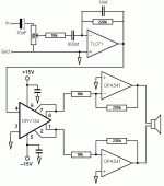
could you draw a diagram to show what you mean? i connect as the diagram i posted (with DRV134), and then to four chips (two paralleled on each side), with the filter network you suggested, on each chip?
It's very common to have a polarised electrolytic cap in the signal path like that. A bipolar is better, I just showed a polarised one so that if you used one you would know which way to connect it.
Bridging *doubles the voltage* which means you *quadruple the power*
Your assumption on how to connect the amps is correct. However, I would strongly advocate that you build the amps as you originally intended, i.e. not as active filters. Also do away with the volume control pot. Then build an active filter using an op-amp. The way you do this is exactly the same as if you had built a power amp, just a smaller chip") So on this one you do include the volume control pot. Now just feed the active filter into the bridging chip as per that schematic you posted.
So on this one you do include the volume control pot. Now just feed the active filter into the bridging chip as per that schematic you posted.
This way avoids each amp having slightly different filter characteristics, saves on parts, and makes it much easier to upgrade later.
Bridging *doubles the voltage* which means you *quadruple the power*
Your assumption on how to connect the amps is correct. However, I would strongly advocate that you build the amps as you originally intended, i.e. not as active filters. Also do away with the volume control pot. Then build an active filter using an op-amp. The way you do this is exactly the same as if you had built a power amp, just a smaller chip
So on this one you do include the volume control pot. Now just feed the active filter into the bridging chip as per that schematic you posted.This way avoids each amp having slightly different filter characteristics, saves on parts, and makes it much easier to upgrade later.
richie00boy said:It's very common to have a polarised electrolytic cap in the signal path like that. A bipolar is better, I just showed a polarised one so that if you used one you would know which way to connect it.
Bridging *doubles the voltage* which means you *quadruple the power*
Your assumption on how to connect the amps is correct. However, I would strongly advocate that you build the amps as you originally intended, i.e. not as active filters. Also do away with the volume control pot. Then build an active filter using an op-amp. The way you do this is exactly the same as if you had built a power amp, just a smaller chip
This way avoids each amp having slightly different filter characteristics, saves on parts, and makes it much easier to upgrade later.
what opamp should i use? OPA627? TL071/2?
I'm a big fan of TL07x and NE553x chips. I use TL07x for just about everything, reserving the NE553x for better stuff or when I need to drive heavier loads (less than about 4k).
You could build the bridging adapter with an op-amp as well - it's only a unity-gain inverter. If you want to use the DRV134 though, that's fine
You could build the bridging adapter with an op-amp as well - it's only a unity-gain inverter. If you want to use the DRV134 though, that's fine
richie00boy said:Good shot kid, I think ya got it
You need to make each of those OPAs 2 paralleled chips, but I know you know that, it's just easier to draw 1
i have just found about 50 TL081s in my scrap bin, can i use these? the maplin catalogue says they are just a lower quality version of the TL071.
ill start building now. thank you again for your help. i will post my results.
richie00boy said:Almost forgot! Make sure you brace that box of yours well - they are gonna be big panels.
i am going to. the box will have 3 panels inside, one accross each plane.
i have some more OPA541s (the AM version). couldnt i use these, with the diagram below, to make a voltage and current limited PSU?
i know it is for the OPA549, but the voltage reulation should work, even if i have to change the resistor values, and i could use perminant resistor instead of the potentiometer to get a fixed output voltage.
the current limit wouldnt work with this circuit, but i am not interested in current limiting.
Attachments
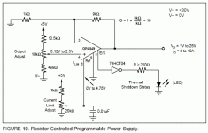
I've only seen the data sheet for the chip you are using in the amp. You could use the chip as a voltage regulator, just check out the data sheet to see what the max current is. Find the safe operating area graph and find the voltage scale. Look on this scale for the voltage that equals Vsupply-Vout, i.e. how much voltage the chip will be dropping, then read across on the load-line to find the max current you can work with. There was no DC load-line on the graph of the data sheet I saw, so go with the one closest to DC (maybe 100ms) and then restrict yourself to half what current you read off.
As to the current limiting bit, providing the pin-out is the same on the two chips and they are comparable in specs, it should work.
As to the current limiting bit, providing the pin-out is the same on the two chips and they are comparable in specs, it should work.
richie00boy said:By EQ, yes, I meant equaliser. I'm a massive fan of the Linkwitz Transform, it's the only EQ worth using IMO. I have designed several PCBs for this kind of thing. A bare LW transform with adjustable subsonic filter and my latest one is as above but with L+R summing inputs, LFE input, adjustable phase control and adjustable low-pass filter as well
Just re-reading some previous posts. Could I have the circuit/PCB design for this/these?

No, I havent finished my filters/LT yet.

Where
F is in hertz
R is in ohms
C is in farads (1,000,000 uF = 1F)
So, the calculations you did should be evident now
Here's a neat, simple trick to make things easier: Instead of ohms, use megohms, and instead farads, use microfarads. This change makes it much easier to calculate the values with less chance of losing your decimal place. The first cancels out the second. !0K is 0.01 megohms and the capacitor is read directly in microfafads. In this case 0.796 uF.
Then there is this handy online calculator: Guitar Pedals: R-C Filter Calculator Good luck and have fun!
- Status
- This old topic is closed. If you want to reopen this topic, contact a moderator using the "Report Post" button.
- Home
- Loudspeakers
- Multi-Way
- Passive line level low and high pass filter help