And where has Papa hidden the (very efficient, because they do not need a big heatsink) output devices ?
Maybe under the capacitors mounted to the bottom of the amp ...
most probably hidden in that nasty IEC mains filter case

most probably hidden in that nasty IEC mains filter case
No way! They're at the bottom of the amp.
")
Then we decided to try to keep that resistance wich doesnot influencing bass response and to add some inductivity.
Inductance tends to sound better than resistance in PS imho.
How much inductance did you use? Core material?
Dear wayne:
Are the other terminals of the sources (the black wire) connected together also ?
Regards,
Claas
Yes if you look close one picture shows it a bit hidden.
Well, I looked carefully at the picture downstairs (see the attachment) and it appears there are 2 pots for
each channel, very close to the Input Cascode Q's.
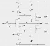
By following the PCB traces on the picture, it also appears Pass Labs has applied the so-called "Cascode Feedback"
enveloping the first and 2nd stages. But I'm not 100 on this as the picture quality is really low. Please see the schematics below.
What needs to be figured out is the electrolytic caps on the main PCB:
Are they in the signal path? or are they PSU/Voltage Reference decouplings.
Any ideas?

each channel, very close to the Input Cascode Q's.
By following the PCB traces on the picture, it also appears Pass Labs has applied the so-called "Cascode Feedback"
enveloping the first and 2nd stages. But I'm not 100 on this as the picture quality is really low. Please see the schematics below.
What needs to be figured out is the electrolytic caps on the main PCB:
Are they in the signal path? or are they PSU/Voltage Reference decouplings.
Any ideas?
Last edited:
Inductance tends to sound better than resistance in PS imho.
How much inductance did you use? Core material?
--------------------------------------------
Thanks for the tip
I am not sure I share your enthusiasm for inductors in the PSU.
My experience has always shown that inductors in the PSU of Power Circuits tend to
seriously compromise high frequency extension and midrange liquidity.
I do not know why?? but I have always gone back to low-value resistors and the sweet tops and liquid mids return.
But you might be right about the bass. The music I listen to contains very little low frequency information.
I built an Aleph 3 clone, with enhanced Open-Loop Gain and completely Single Ended output biased at 6 amps.
Inductors in the PSU of this amp did not sound good at all. I tried many different inductors (lost a lot of money) - Monacor, Mudorf, Jensen, Hammond, Signal, etc...
Everytime I went back to resistors, the mids and highs got their sparkle back.
Caps only were good, but R-C--R-C was the best.
Last edited:
-------------------------------------------------The only conflict, as far as the Output Devices being speculated as HockeyPucks is concerned is that they are rated at about 560 Watts whereas Pass XA25 says 700 Watt devices.
Yes, that is true. I commented on that earlier:
http://www.diyaudio.com/forums/pass-labs/299383-pass-xa25-24.html#post5083446.
The ouput devices are probably not the correct ones, but I included them just for the sake of having something to work with.
Hopefully with everyones help, we can arrive at a good approximation to the XA-25 circuit.
I would like to know more about the electrolytic caps on the main (upper) PCB.
What are your thoughts?
Last edited:
Looking at this picture, I noticed some circuitry on each side of the bottom PCB.
Those might be the bias generators.
I do not see any degeneration resistors for the 2nd stage Q's.
However they might be there, since it would be very difficult to keep the bias fairly constant without them.
The electrolytic caps are still a mystery. I do not see any TL431 on the PCB, so the reference voltages for the Cascode devices might be
done with resistors or zeners, but it is not possible to decipher it from the attached pic.
Would appreciate any comments.
Last edited:
--------------------------------------------
My experience has always shown that inductors in the PSU of Power Circuits tend to
seriously compromise high frequency extension and midrange liquidity.
I do not know why??
Interesting. I guess it comes down to specifics. I tried using chokes in tube circuits almost 20 years ago and was immediately disappointed for reasons similar to what you state. Since then i have learned that everything matters: winding geometry, multi sectioning and especially core material.
do you want original schematic ?
I want complete amp please!
Maybe two, one for my wife!
Alexiss, we made intentionally a separate thread the "F4 beast builders" thread, to discuss possible circuits with the pucks, of course as close as possible to what Nelson gave us already, but without the intention to make a 100% clone.
Or ESP.Reverse engineering is sooooooo 2004. The next wave is precognitive engineering
I want complete amp please!
Alexiss, we made intentionally a separate thread the "F4 beast builders" thread, to discuss possible circuits with the pucks, of course as close as possible to what Nelson gave us already, but without the intention to make a 100% clone.
---------------------
Thank you all for your inputs ;- Very much appreciated.
I have gone through the F4 Beast thread, and as I have stated earlier on this thread, the circuits presented
there are a good basis to start on and I have used many of the good ideas presented there.
But this thread is about the new class of amplifiers from Pass Labs starting with XA25.
As mentioned earlier, it has been a great exercise to see the "evolution" of Mr Pass's designs through the decades, starting
from complex, to very simple SE, and then to slightly more complex Push/pull.
The purpose of the discussions here are - once again - mental exercise, and reverse engineering a product is always challanging,
specially when there is so little info available.
I think Zen Mod said it very nicely that it is interesting to understand the circuit design rather than making copies of it.
I sincerely hope we are not insulting anyone here.
Thank you for great and many times humorous comments. It is a reminder not to take things too seriously :-D
Cheers
Last edited:
Anyways, back to the circuit:
I have thought about it a lot and I am almost certain degenerative feedback is used in the 2nd gain stage.
It would otherwise lead to serious (and unnecessary) drift and function instability.
So the proposed schematics is once again modified to this:
I have thought about it a lot and I am almost certain degenerative feedback is used in the 2nd gain stage.
It would otherwise lead to serious (and unnecessary) drift and function instability.
So the proposed schematics is once again modified to this:
Attachments
The way the output followers are connected to the FE and biased in the F4 Beast thread is (according to my opinion) not the way XA-25 is implemented.
Therefore I think the electrolytic caps on the main upper PCB are PSU decoupling caps, as I do not find anything else to contradict that theory.
There seem to be no TL431s or any IC references on the board.
Being somewhat familiar with previous designs of Mr Pass, the voltage references might be comprised of
zeners or resistors.
Let's go with resistors for now.
The updated schematics is:
Last edited:
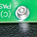
Supposedly this is from the inside of the XA25...
Thank you very much Dennis for this detail....
if others follow during the next years, I will make a big puzzle out of it and put it on my wall.....
- Home
- Amplifiers
- Pass Labs
- Pass XA25?