> but what the positive results be compared to using a high performance opamp?
The circuit comes from Nelson (basically), so I guess he is the right one to ask.
For me, it was just a packaging challenge that I took on and realised.
But perhaps I can name one major difference to an opamp IC -- All Class A operation.
I guess on the Pass forum, we are all Class A fans ??
")
> Have you ever considered to make a current feedback "opamp"?
Would you not agree that we generally have more applications for an OPA627 than say an AD844 ?
Having said that, if you have a similarly simple circuit, I might be tempted to take on the challenge for the layout, just for mental jogging.
But I have no plans to build anymore of these at the moment, other than finishing those I have on hand and test them in the phono preamp as posted.
> I love the shape of top layer - reminds me of '70s hand-drawn PCBs,
Thank you. Not quite hand drawn, but Autocad and photo etched.
> is that a FET follower fed from a CCS that you're suggesting?
Yes, using a matched FET as CCS to the negative rail.
Patrick
The circuit comes from Nelson (basically), so I guess he is the right one to ask.
For me, it was just a packaging challenge that I took on and realised.
But perhaps I can name one major difference to an opamp IC -- All Class A operation.
I guess on the Pass forum, we are all Class A fans ??
> Have you ever considered to make a current feedback "opamp"?
Would you not agree that we generally have more applications for an OPA627 than say an AD844 ?
Having said that, if you have a similarly simple circuit, I might be tempted to take on the challenge for the layout, just for mental jogging.
But I have no plans to build anymore of these at the moment, other than finishing those I have on hand and test them in the phono preamp as posted.
> I love the shape of top layer - reminds me of '70s hand-drawn PCBs,
Thank you. Not quite hand drawn, but Autocad and photo etched.
> is that a FET follower fed from a CCS that you're suggesting?
Yes, using a matched FET as CCS to the negative rail.
Patrick
Most opamps work in class A under normal working conditions except for LM324/358, which works in class CEUVL said:But perhaps I can name one major difference to an opamp IC -- All Class A operation.


 This is rather easy to observe. You'll get heavy cross-over distortion from this opamp, very educational I'd say. Class C is even worse than class B.
EUVL said:The circuit comes from Nelson (basically), so I guess he is the right one to ask.
The circuit is not original with me - it's a classic.
You have absolutely no class A in LM324. It really runs in class C. Bob Pease demonstrated how to bias LM324 into class A in a video available at National. Maybe someone can find it. He made it very clear how it looked like "before" and "after"flg said:It's a single supply, class AB. '83-'88 I was the Motorola Device Engineer for their OpAmp product line.
Educational
> The circuit is not original with me - it's a classic.
Topology is a classic. Choice of component and bias was still very largely influenced by your publication.
> Most opamps work in class A under normal working conditions.
First two stages perhaps ?
I cannot recall seeing an opamp with Iq in the order of 40mA.
In the current design, the output stage, being a source follower with a CCS bias, will ONLY work in Class A and not even Class AB. Max Iout is limited by Idss, say around 15mA.
Patrick
Holger,
At the moment, I am trying to source another low-noise JFET similar to the BF862 but with a lower Idss. The part exists, but a source for small quantities (<5000) proves to be very illusive. While I can couple with the heat from the BF862s, the DC drift is a bit too high for my taste, especially with high gain applications like phono preamps. So a little patience, also for Steen.
I know that you have been involved in a German group buy some time ago for 1000 BF862s. If you wish to try one for yourself, you can PM me for details, incl PCBs.
Patrick

 .
.Buffer-Filter-Buffer Phono for MC
.
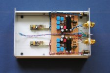
After almost a year's delay, and a change of layout to add source degeneration, the discrete opamp phono is finally finished.
The opamps now use BF862s for N-devices only, with varying degrees of degeneration. Thermal drift is a small problem in a high-gain (40dB) buffer that I used for the phono circuit, so some form of DC servo is necessarily. I simply use a cap on the feedback leg to Gnd.
I could have trimmed for steady state by adding a trimmer between pins 7 & 8, but decided that a cap is better in that I do not need to wait for steady state. But for the purist using the opamp for gain of 10 or less, there is little problem achieving single-digit mV offsets.
The circuit used was what I am using currently, as the exercise was meant to compare opamps in a specific application. The input stage is a non-inverting amp with a gain of 100, followed by a purely passive RIAA filter, and then by another buffer with gain of 100. In the reference built, I am using AD797 for the input stage and OPA637 for the output.
This is just a scratch-built, using a simple aluminium casing I have lying around, without much attention to wiring, etc.
The result : a very obvious improvement to the AD797 / OPA637 combination, especially on clarity, female vocal, string instruments, and placement.
All in all, I am very satisfied with the results, and should encourage anyone to give it a trial.
Patrick
.
After almost a year's delay, and a change of layout to add source degeneration, the discrete opamp phono is finally finished.
The opamps now use BF862s for N-devices only, with varying degrees of degeneration. Thermal drift is a small problem in a high-gain (40dB) buffer that I used for the phono circuit, so some form of DC servo is necessarily. I simply use a cap on the feedback leg to Gnd.
I could have trimmed for steady state by adding a trimmer between pins 7 & 8, but decided that a cap is better in that I do not need to wait for steady state. But for the purist using the opamp for gain of 10 or less, there is little problem achieving single-digit mV offsets.
The circuit used was what I am using currently, as the exercise was meant to compare opamps in a specific application. The input stage is a non-inverting amp with a gain of 100, followed by a purely passive RIAA filter, and then by another buffer with gain of 100. In the reference built, I am using AD797 for the input stage and OPA637 for the output.
This is just a scratch-built, using a simple aluminium casing I have lying around, without much attention to wiring, etc.
The result : a very obvious improvement to the AD797 / OPA637 combination, especially on clarity, female vocal, string instruments, and placement.
All in all, I am very satisfied with the results, and should encourage anyone to give it a trial.
Patrick
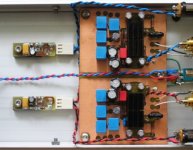
Attachments
A close-up on the PCBs, showing a pair of 7812/7912 size and pin-compatible, low-noise-zener-based cap multipliers.
The external power supply is a wall-plug unit using 10VA toroidal Tx, BVV26C diodes, and a pair of 7818/7918 as pre-regs.
Patrick
The external power supply is a wall-plug unit using 10VA toroidal Tx, BVV26C diodes, and a pair of 7818/7918 as pre-regs.
Patrick
Attachments
Hi Patrick
I wonder why so few people are interested in your projects (maybe for the small dimensions, the average age of the DIYers is not so low ).
As I love simplicity, and I have to use an op-amp as a balanced-to-single-ended converter, your project is really intriguing.
Could you be so kind to confirm the updated schematic (is it all-BF862 now?)
Many Thanks
Guido
I wonder why so few people are interested in your projects (maybe for the small dimensions, the average age of the DIYers is not so low
).As I love simplicity, and I have to use an op-amp as a balanced-to-single-ended converter, your project is really intriguing.
Could you be so kind to confirm the updated schematic (is it all-BF862 now?)
Many Thanks
Guido
I've stumbled across this and am very interested in trying it out. Fits in the with the next design I want to play with.
However, I'm trying to sim it and my sim is blowing up in nice wonderful ways.
I know this is most likely a user issue, but I can seem to figure it out. Either that or easiest 2.1MV creator ever. And I'm not sure why replacing Q5 with a constant current source doesn't seem to work either.
However, I'm trying to sim it and my sim is blowing up in nice wonderful ways.
An externally hosted image should be here but it was not working when we last tested it.
I know this is most likely a user issue, but I can seem to figure it out.
Either that or easiest 2.1MV creator ever. And I'm not sure why replacing Q5 with a constant current source doesn't seem to work either.- Status
- This old topic is closed. If you want to reopen this topic, contact a moderator using the "Report Post" button.
- Home
- Amplifiers
- Pass Labs
- Pass Discrete Opamp in DIP-8 Package