I forgot to mentioned that its a 110v bulb and failure occurs during startup without any changing of input leads.
Re-reading your previous post, it may be that you are
simply exceeding the dissipation limit of the device with
your cooling. At 3.7 amps what is the voltage from Drain
to Source and how hot is it?

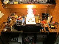
My delite amp ,just completed with help of Tony
Hi NeLson,
After Hookup ,found that the sound is abit softer than normal power amp, is this normal ? for C4 used is 10uf , output cap is 10,000 uf.
The dain vlotage is 25 VDC , using 60V AC .
Thanks
It is not a normal power amp. Assuming a reasonably
low source impedance, the bandwidth will be quite wide,
on the order of a couple hundred kiloHertz, but it will still
sound a little soft compared to the usual power amp,
with less bandwidth and more complicated circuits and
of course feedback. This is a fairly common phenomenon.
low source impedance, the bandwidth will be quite wide,
on the order of a couple hundred kiloHertz, but it will still
sound a little soft compared to the usual power amp,
with less bandwidth and more complicated circuits and
of course feedback. This is a fairly common phenomenon.
It is not a normal power amp. Assuming a reasonably
low source impedance, the bandwidth will be quite wide,
on the order of a couple hundred kiloHertz, but it will still
sound a little soft compared to the usual power amp,
with less bandwidth and more complicated circuits and
of course feedback. This is a fairly common phenomenon.
thanks Mr.Pass, BTW ,what is the best value for input capacitor ?
Hi Nelson,
It's actually my Delite JFet amplifer... We've already installed a soft start circuit and it's been working great for the last month, no more failures... Thank you so much for sharing this wonderful design with us..
It's actually my Delite JFet amplifer... We've already installed a soft start circuit and it's been working great for the last month, no more failures... Thank you so much for sharing this wonderful design with us..
Re-reading your previous post, it may be that you are
simply exceeding the dissipation limit of the device with
your cooling. At 3.7 amps what is the voltage from Drain
to Source and how hot is it?
thanks Mr.Pass, BTW ,what is the best value for input capacitor ?
It's not important - use whatever you like, but I would
look in the range of 10 uF or more.
It's not important - use whatever you like, but I would
look in the range of 10 uF or more.
Thanks Mr Pass.
What value for C4?
Have you tested the R085's for Gate current?
How about using a Gate stopper at 100 ohms or so?
................
Re-reading your previous post, it may be that you are
simply exceeding the dissipation limit of the device with
your cooling. At 3.7 amps what is the voltage from Drain
to Source and how hot is it?
Like what other fellow forummers has replied:
1) What value for C4? --> 10uF
2) Have you tested the R085's for Gate current? --> Nope. May I know how does it matters?
3) How about using a Gate stopper at 100 ohms or so? --> I think it will help but to what extend? Lowers the chance of any static killing the R085 at the input to the gate? Is there any demerit for this?
4) At 3.7 amps what is the voltage from Drain to Source and how hot is it? -->Vds = 25VDC. The heatsinks are only warm, putting my hand on it for 5sec is fine, guess its around 55~60DegC.
Like what BTW mentioned, putting a PSU delay turn-on helps. But when changing the RCA input cable, the lamp is glows brighter than norm and goes back to norm brightness state after the change of RCA cable.
So, in this case, does putting a Gate stopper help? Just curious, what should the wattage of the Gate stopper be, 0.5W enough?
Thanks Nelson.
what should the wattage of the Gate stopper be, 0.5W enough?
0.5 W as gate stopper is plenty, gate draws no current
Hannes
2) Have you tested the R085's for Gate current? --> Nope. May I know how does it matters?
3) How about using a Gate stopper at 100 ohms or so? --> I think it will help but to what extend? Lowers the chance of any static killing the R085 at the input to the gate? Is there any demerit for this?
4) At 3.7 amps what is the voltage from Drain to Source and how hot is it? -->Vds = 25VDC. The heatsinks are only warm, putting my hand on it for 5sec is fine, guess its around 55~60DegC.
Like what BTW mentioned, putting a PSU delay turn-on helps. But when changing the RCA input cable, the lamp is glows brighter than norm and goes back to norm brightness state after the change of RCA cable.
2) Unlike Mosfets, Jfets have some Gate current, and it
varies from part to part and under different voltages,
current and temperature. If the Gate current is excessive
the bias may be thrown off into the high impedance input
resistor.
3) If the bulb gets brighter without an input connection,
then something's going on. It might be high frequency
oscillation, or maybe your input cap is leaking.
4) 3.7A at 25 volts is more than 90 watts. I think this
results in a short life span - I wouldn't exceed 50 W for
these parts, and I usually keep it down around 20-30 W
Nelson Pass;243612 but it will still sound a little soft compared to the usual power amp :cool:[/QUOTE said:This is exactly how i would put it, it sounds really good with fostex horns (esp the cheaper ones that can tend towards edginess).
Nelson, Thanks for the advise.2) Unlike Mosfets, Jfets have some Gate current, and it
varies from part to part and under different voltages,
current and temperature. If the Gate current is excessive
the bias may be thrown off into the high impedance input
resistor.
3) If the bulb gets brighter without an input connection,
then something's going on. It might be high frequency
oscillation, or maybe your input cap is leaking.
4) 3.7A at 25 volts is more than 90 watts. I think this
results in a short life span - I wouldn't exceed 50 W for
these parts, and I usually keep it down around 20-30 W
Hey guys,
I finished rebuilding my Delite. Attached are some pics. I've tried a CLC
supply with some random inductors that were lying around. It sounds
much much better with a CLC than a CRC.
After a really long time I was actually getting lost in the music rather
than listening for usual audiophile things. There is something about
single-ended feedback designs that renders our THD meters completely
useless. I have a MyRefC that checks all the boxes and has much lower
THD, but it is not even half as musical as the Delite.
It did sound 'soft' like others have expressed here... it seems to me that
the treble is rolled off. What would cause this? For the output cap, I have
a 1,500 uF Pany paralled with a 1uF no name.
Attachments
Last edited:
Ok... the drain voltage had dropped to 14V when I moved the
amp from the test bench to the listening room. To fix this, I used
the schematic from fig.10 in the Delite article to adjust the drain
voltage and readjusted it after half an hour.
This cured the rolled off treble. The edges are still rounded, but
that's probably the single-ended nature more than anything else.
I'm planning to increase the total capacitance in the PS in a
bid to reduce hum. It is currently at 20,000uF.
After the rectifier, I'm getting close to 95V. What would you
recommend as the minimum capacitor voltage rating for this
duty? My current caps are rated at 200V.
I'd stay with what you have in already and try to find a large value choke with
sufficient current rating to stick between the extra cap. I think standard voltage
increments would be 150V and then the next higher voltage is 200V.
The 200V is plenty but I've heard of the practice of trying to run caps at about
75%-80% of rating, so the 150V rating would probably work better.
I think it has something to do with keeping the caps charged so that they don't
attempt to reverse polarity or something?
What is the capacitance of the additional caps? 20,000uF also?
- Home
- Amplifiers
- Pass Labs
- Pass "DeLite" Amp from BAF