I did take the advice from those that offered it, the 10K pot is at the output of the P1.7.
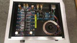
Anyone using the KK-PCB PCBs be very careful with the PCB mounting as it is very easy to short tracks to the chassis through the mounting holes. Either use insulated pillars or insulating washers.
Anyone using the KK-PCB PCBs be very careful with the PCB mounting as it is very easy to short tracks to the chassis through the mounting holes. Either use insulated pillars or insulating washers.
Last edited:
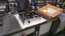
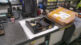
Those cases are being advertised on E-Bay, they are not too badly priced either.
They originate in China but we have a supplier in Germany.
215*70*228mm Aluminum enclosure DAC case amplifier chassis DIY BOX HIFI house | eBay
I bought three of them for my Pearl 2 build as well as this one, the link above might be for one of the other cases.
They originate in China but we have a supplier in Germany.
215*70*228mm Aluminum enclosure DAC case amplifier chassis DIY BOX HIFI house | eBay
I bought three of them for my Pearl 2 build as well as this one, the link above might be for one of the other cases.
Last edited:
Incidentally I decided to replace the thermistor on the PSU PCB with a short as I thought 10R might cause grounding issues with my grounding arrangement.
The XLR sockets are all grounded to the case. No screens are subsequently connected to the PCBs. The main amplifier 0V has to connect to the chassis, this is done at the PSU.
The XLR sockets are all grounded to the case. No screens are subsequently connected to the PCBs. The main amplifier 0V has to connect to the chassis, this is done at the PSU.
I just checked resistance in situ from ztx450 base to irf630 source and found all values on both channels about 221R as expected.
Ok, I've taken a bit more time to look at the schematic and ponder what could be going on. It looks like the bottom 610s are shorted. You can check this with an ohm meter.
We have 5.3 volts across the source resistor. This equates to about 160ma for a 33 ohm resistor. Since the circuit operates with 2 current sources of 30ma ( upper current source (9610)with 22 ohm R source) and 20ma ( lower 610 with 33ohm R source). The 10ma difference between the 2 currents flows through the parallel 4.75K/10k pair of resistors. and should give about 32vdc on the output Caps.
So how is 160ma flowing? Perhaps it's not. It's difficult to troubleshoot this remotely but I would check the value of the source resistors with an ohm meter. Perhaps they are 331 ohms rather than 33.1 or perhaps the value of the 22 ohm resistors is not right. There also could be a defect in the board somewhere or a short between 2 solder pads etc. If you check the bottom 610s with an ohm meter they may be shorted and need replacement. The .79volt base voltage on the ztx450 indicates a lot of base current from the 5.2volts in series with 221 ohms to the base. It is trying to turn off the 610 but it is still conducting.
I hope this is some help to you. Problems with the board could be hard to find. I know you have checked the passive components but there is clearly something wrong with either the board or the active components or their orientation.
I did take the advice from those that offered it, the 10K pot is at the output of the P1.7.
Anyone using the KK-PCB PCBs be very careful with the PCB mounting as it is very easy to short tracks to the chassis through the mounting holes. Either use insulated pillars or insulating washers.
i see you have mounted the 2k gain resistors and you have all switches open. that will give you a very low gain. i ended up shorting those 2K gain resistors and all switches open to get the gain i needed (26db gain in Power amp).
Problem solved!
Thanks for your help Bfpca, I solved the problem!
I checked and rechecked all resistors and caps and only really had the active devices and the board itself left to check. I did not have a schematic that contained the part numbers used on KK's board, so I spent a couple of hours manually tracing the (single sided) pcb to determine part numbering. Having done that enabled me to check known resistances anywhere in the circuit (rather than just the parts themselves) and I found a problem with the ground connection on one of the two channels. On KK's board a jumper is required to connect two parts of the ground circuit but the pad of one of them was not connected to the trace (quite a bit of the amp's circuitry was not grounded!). Perhaps too much heat was applied and the trace lifted? Whatever the case, I was able to by-pass the faulty connection and all voltages are as they should be. The amp is now connected to my DIY Aleph J in my study and playing beautiful music!
First impression is that it sounds more refined than the B1 and BA3 I used previously. I will leave it on for a couple of days to burn in and see how it develops. Then I really have to start thinking about the layout of the front panel. It is the first time I will get a front panel done, so I really need to make sure I figure out exactly what I need to do to get the OLED display mounted properly on the 10mm panel, etc. Should keep me busy for a while.
Thanks Nelson for a great amp!
Ok, I've taken a bit more time to look at the schematic and ponder what could be going on. It looks like the bottom 610s are shorted. You can check this with an ohm meter.
We have 5.3 volts across the source resistor. This equates to about 160ma for a 33 ohm resistor. Since the circuit operates with 2 current sources of 30ma ( upper current source (9610)with 22 ohm R source) and 20ma ( lower 610 with 33ohm R source). The 10ma difference between the 2 currents flows through the parallel 4.75K/10k pair of resistors. and should give about 32vdc on the output Caps.
So how is 160ma flowing? Perhaps it's not. It's difficult to troubleshoot this remotely but I would check the value of the source resistors with an ohm meter. Perhaps they are 331 ohms rather than 33.1 or perhaps the value of the 22 ohm resistors is not right. There also could be a defect in the board somewhere or a short between 2 solder pads etc. If you check the bottom 610s with an ohm meter they may be shorted and need replacement. The .79volt base voltage on the ztx450 indicates a lot of base current from the 5.2volts in series with 221 ohms to the base. It is trying to turn off the 610 but it is still conducting.
I hope this is some help to you. Problems with the board could be hard to find. I know you have checked the passive components but there is clearly something wrong with either the board or the active components or their orientation.
Thanks for your help Bfpca, I solved the problem!
I checked and rechecked all resistors and caps and only really had the active devices and the board itself left to check. I did not have a schematic that contained the part numbers used on KK's board, so I spent a couple of hours manually tracing the (single sided) pcb to determine part numbering. Having done that enabled me to check known resistances anywhere in the circuit (rather than just the parts themselves) and I found a problem with the ground connection on one of the two channels. On KK's board a jumper is required to connect two parts of the ground circuit but the pad of one of them was not connected to the trace (quite a bit of the amp's circuitry was not grounded!). Perhaps too much heat was applied and the trace lifted? Whatever the case, I was able to by-pass the faulty connection and all voltages are as they should be. The amp is now connected to my DIY Aleph J in my study and playing beautiful music!
First impression is that it sounds more refined than the B1 and BA3 I used previously. I will leave it on for a couple of days to burn in and see how it develops. Then I really have to start thinking about the layout of the front panel. It is the first time I will get a front panel done, so I really need to make sure I figure out exactly what I need to do to get the OLED display mounted properly on the 10mm panel, etc. Should keep me busy for a while.
Thanks Nelson for a great amp!
Good news! There were some strange voltage readings there. The open ground connection explains that.
I have my boards almost completed. Still have a lot of work to do on chassis etc.
Good luck with your build!
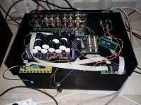
I used different types of wire to connect the various inputs to the inputselection board. This makes an easy way to test the influence of using different gauges and types of wire
")
I have been listening to the amp for a few hours today and it sounds great, although at the moment I am listening in my study setup with not-so-revealing speakers. The amp stays there till everything is finalised before migrating to the living room.
Something that needs solving is a volume related problem. When I change volume (up as well as down) I get some distortion (only during the actual changeover). Perhaps due to digitalgnd and audiognd connected through ferrite beads on Dantimax input and volume board? I have asked Mikkel if he is familiar with the problem before I start looking for the cause. Perhaps just removing the ferrite connection is all that is needed. Anyway, while I keep the volume constant it sounds great, so I hope it will be relatively easy to fix.
you should only have the ferrite beed on 1 of the boards. otherwise you get a groundloop.
Hi AudioSan,
Thanks for your suggestion. I understand about the groundloop but there is no hum or anything like that so I assume it is not a "loop" problem.
There is some distortion when the volume is changed but none once the volume stays the same. I am powering my Dantimax boards from a dedicated PSU (separate from the amp's PSU's) and left it floating. I had not realised that the Dantimax boards had a connection between digitalgnd and audiognd until I had a closer look at the schematic this evening. I never realised the significance of the ferrite beads when I soldered them ages ago.
I will try changing the grounding to see if it solves the problem.
I'm planning to build myself an Preamp, and wonder if someone could tell me the difference between 1.7 and for example a hotrod DCB1 preamp ?
Is there any sound quality differences ?
I can't say anything for or against the DCB1 bevcause I have never heard one, but I have built the original B1 (using pcb and jfets from Pass Labs) and just completed the Aleph P1.7.
An important difference between the two is that the Aleph P1.7 has gain, up to about 20dB, while the B1 has none. If you need gain the B1 is not for you. I assume (but do not know for sure) the DCB1 also has no gain.
For the Aleph and B1 builds I used the same RN55D Dale resistors, but the 10uF caps on the Aleph are relatively cheap Audyn Cap MKP-QS, while I used the more expensive 1uF and 10uF Clarity Cap SA in the B1. For the B1 I assembled an RN55D based 25k stepped shunt attenuator and the Aleph P1.7 uses a Dale RN55D based Dantimax attenuator, so again the same resistors in the signal path.
To me the sound of the Aleph P1.7 is much more refined than the B1. I have not yet tried a good linear PSU for the B1 but am using a 24V external SMPS so that could explain some of the difference.
If I were you I would build the B1 first, it is very easy and if you do not use exotic parts relatively cheap. Like me, it will give you something to listen to while you are building an Aleph P1.7!
@albertNL
Thanks for the info, I will probably build both, and start with B1-Hotrod version.
Meanwhile I'm working on the schematic for Aleph 1.7, so I can make my own PCBs.
Where did you find the LCD and relays for input/output and volume ?
Do you have more pictures of your build?
regards
Patrik
Thanks for the info, I will probably build both, and start with B1-Hotrod version.
Meanwhile I'm working on the schematic for Aleph 1.7, so I can make my own PCBs.
Where did you find the LCD and relays for input/output and volume ?
Do you have more pictures of your build?
regards
Patrik
- Home
- Amplifiers
- Pass Labs
- Pass Aleph P 1.7 preamp builders thread